
User Guide


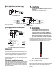
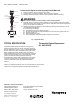
Table Of Contents

AM-1 SERIES “R MODEL” - HEATING ONLY
3 62-3106—01
Mixing Applications (Constant Supply
Temperature)
Fig. 2. Single Loop.
CAUTION
Do Not Install Pump Between Connection “A” and
Heat Source.
The installation of the pump at this point would result in
NO FLOW
through the radiation loop(s).
Each loop operates at a different temperature.
Fig. 3. Multiple Loops.
Diverting Application (Constant Return
Temperature)
Fig. 4. Single Loop for Multiple Loops.
Fig. 5. AM-1 Primary/Secondary Application.
OPERATION
The AM-1 Series valve provides for automatic operation
through the use of a thermostatic element in the product. The
element will control the mixing of the hot and cold supply water
to provide mixing tempered water to connected water control
devices. This provides constant water temperature under
different working conditions.
Thermostrip temperature indicator easily indicates water
temperature 105° - 180° F (41° - 82° C) for accurate control
and quick set-ups.
Thermostrip Installation Instructions
Clean pipe to mix outlet of valve and firmly apply Thermostrip.
Flow water and adjust mixed outlet temperature for desired
setting range. Actual mixed water temperature is indicated in
green with 5° F (15° C) increments. Blue means slightly lower
and brown slightly higher.
WARNING
To ensure proper application and usage, the
Honeywell AM-1 “R” model mixing valves are
designed for HEATING ONLY applications and
should never be used for Domestic Hot Water as
temperature and product usage far exceed safe
water temperature limitations. Water temperatures
above 120° F (49° C) can cause serious injury.
Mixing valve temperature setting should be done
by licensed contractor per local code requirement.
Thermal temperature indicator strip is One Time use only for
initial system temperature setting. Check date code printed on
temperature strip to ensure temperature reading accuracy.
Fig. 6. Thermostrip Temperature Indicator.
VALVE MAINTENANCE
Hard water conditions may results in scale deposits causing
binding of internal parts in extreme cases. Cleaning the internal
parts will usually restore the valve operating conditions. In
some cases it may be necessary to replace the lower
assembly.
SuperVent
HEAT
SOURCE
EXPANSION
TANK
AM SERIES
PUMP
PUMP
H
A
C
M(2)
ZZZ
(BOILER,
WATER
HEATER,
etc.)
ZONE
VALVE S
RADIANT
FLOOR LOOP
M25429
SuperVent
HEAT
SOURCE
EXPANSION
TANK
AM SERIESAM SERIES
PUMP
PUMP
PUMP
PUMP
H
AA
C
H
C
MM (2)
(1)(1)
(2)
ZZ ZZZ Z
(BOILER,
WATER
HEATER,
etc.)
ZONE VALVES
RADIANT
FLOOR LOOP
ZONE VALVES
RADIANT
FLOOR LOOP
M25430
SuperVent
HEAT
SOURCE
EXPANSION
TAN K
AM SERIES
PUMP
PUMP
H
C
H
C
M
(2)
ZZZ
(BOILER,
WATER
HEATER,
etc.)
ZONE VALVES
RADIANT
FLOOR LOOP
M25431
SuperVent
HEAT
SOURCE
EXPANSION
TANK
AM SERIES
PUMP
PUMP
PUMP
H
C
M
(2)
(BOILER,
WATER
HEATER,
etc.)
SUPPLY
HEADER
RETURN
HEADER
M25432
°F
°C
175
79
170
77
165
74
160
71
155
68
150
66
145
63
140
60
135
57
130
54
125
51
120
49
115
46
110
43
105
41
Thermostrip
Accuracy expires
after MMYYY
180
82
M25433