
Install Instructions
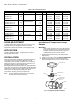
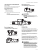
Table Of Contents

AM-1 SERIES “R MODEL” - HEATING ONLY
© 2020 Resideo Technologies, Inc. All rights reserved.
This product is manufactured by Resideo Technologies, Inc. and its affiliates.
www.resideo.com
Resideo Technologies, Inc.
1985 Douglas Drive North, Golden Valley, MN 55422
1-800-468-1502
62-3106—04 M.S. Rev. 03-20 | Printed in United States
Thermal temperature indicator strip is One Time use only for
initial system temperature setting. Check date code printed
on temperature strip to ensure temperature reading accuracy.
Thermostrip only included in models without the temperature
gauge.
Fig. 7. Thermostrip Temperature Indicator.
VALVE MAINTENANCE
Hard water conditions may results in scale deposits causing
binding of internal parts in extreme cases. Cleaning the internal
parts will usually restore the valve operating conditions. In
some cases it may be necessary to replace the lower assembly.
To Clean and/or Replace the Lower Assembly
Shut Off Water and:
1. With a screwdriver remove screw and hand wheel.
2. Unscrew lower nut (counterclockwise). This removes
top assembly.
3. Brass top assembly will pop up. Remove lower
assembly, diffuser and spring.
WARNING
Do not use solvents or scratch metallic / Teflon
coated surfaces.
4. Carefully remove any scaling (calcium deposits) or
foreign particles from valve seat and other internal
parts. Use vinegar to remove calcium. Soak parts until
calcium becomes soft and can be scrubbed and
washed off.
5. Replace cleaned spring, diffuser and lower assembly
following instructions below or use new replacement
kit assembly.
a. Insert spring onto diffuser.
b. Insert diffuser with spring end first into body.
c. Fit valve top assembly into lower assembly and
insert into valve. Tighten lower nut.
d. Tightening upper nut.
e. Place handwheel on valve.
f. Turn handwheel to desired temperature setting and
insert screw.
Fig. 8. Exploded View
TYPICAL SPECIFICATION
Temperature Setting Range (as required, see page 1),
Maximum Pressure rating of 150 psi (1034 kPa), Maximum
Hot inlet temperature of 212° F (100° C), Nickel plated
Brass/Bronze construction, Teflon coated valve body wear
surface, Teflon coated brass shuttle, EPDM O-rings,
proportional design (simultaneous control of hot and cold
ports), with either sweat union, propress union, NPT (female)
union or union PEX connections. Valve for domestic hot
water applications shall have temperature lock. Design shall
be straight thru, with hot and cold ports at the same level.
The design shall permit easy access for maintenance, with
replaceable thermostatic element.
Teflon
®
is a registered trademark of E.I. Du Pont De Nemours and Company.
°F
°C
175
79
170
77
165
74
160
71
155
68
150
66
145
63
140
60
135
57
130
54
125
51
120
49
115
46
110
43
105
41
Thermostrip
Accuracy expires
after MMYYY
180
82
Table 2. Replacement Parts.
Part No. Description
AM-1-025RP Thermostatic Element Replacement Kit
AM1-TG100-US-LF/U 1/2" AM1 Temp Gauge Tail PC w/Sweat
AM1-TG101-US-LF/U 3/4" AM1 Temp Gauge Tail PC w/Sweat
AM1-TG102-US-LF/U 1" AM1 Temp Gauge Tail PC w/Sweat
TG200-UT/U Thermometer, 2" Dial w/ Threaded Well
TG250-UT/U Thermometer, 2.5" Dial w/ Threaded Well
M23941A
LOWER ASSEMBLY
HANDWHEEL
DIFFUSER
SPRING
VALVE BODY
TOP ASSEMBLY
LOWER NUT
UPPER NUT
O RING
RETAINING RING
C
MIX
H