
Install Instructions
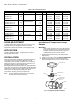
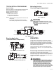
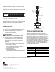
Table Of Contents

AM-1 SERIES “R MODEL” - HEATING ONLY
3 62-3106—04
TYPICAL INSTALLATION DIAGRAMS
Space Heating
Boiler must operate at a water temperature higher than the
desired temperature in the heating system in order to
perform at maximum efficiency.
Example: Radiant floor heating.
SYMBOLS
1 = Check Valve/Flow Check
2 = Alternate Pump Location
T = Pump Control Thermostats
NOTES:
• Install recirculation pump between last fixture and
water heater.
• Use a pump control thermostat where shown.
Recirculation pump should not run continuously.
Mixing Applications
(Constant Supply Temperature)
Fig. 3. Single Loop.
CAUTION
Do Not Install Pump Between Connection “A” and
Heat Source.
The installation of the pump at this point would result
in NO FLOW
through the radiation loop(s).
Each loop operates at a different temperature.
Fig. 4. Multiple Loops.
Diverting Application
(Constant Return Temperature)
Fig. 5. Single Loop for Multiple Loops.
Fig. 6. AM-1 Primary/Secondary Application.
OPERATION
The AM-1 Series valve provides for automatic operation
through the use of a thermostatic element in the product. The
element will control the mixing of the hot and cold supply
water to provide mixing tempered water to connected water
control devices. This provides constant water temperature
under different working conditions.
Thermostrip temperature indicator easily indicates water
temperature 105° - 180° F (41° - 82° C) for accurate control
and quick set-ups.
Thermostrip Installation Instructions
Clean pipe to mix outlet of valve and firmly apply
Thermostrip. Flow water and adjust mixed outlet temperature
for desired setting range. Actual mixed water temperature is
indicated in green with 5° F (15° C) increments. Blue means
slightly lower and brown slightly higher.
WARNING
To ensure proper application and usage, the AM-1 “R”
model mixing valves are designed for HEATING ONLY
applications and should never be used for Domestic
Hot Water as temperature and product usage far
exceed safe water temperature limitations. Water
temperatures above 120° F (49° C) can cause serious
injury. Mixing valve temperature setting should be done
by licensed contractor per local code requirement.
SuperVent
HEAT
SOURCE
EXPANSION
TANK
AM SERIES
PUMP
PUMP
H
A
C
M(2)
ZZZ
(BOILER,
WATER
HEATER,
etc.)
ZONE
VALVES
RADIANT
FLOOR LOOP
M25429
SuperVent
HEAT
SOURCE
EXPANSION
TANK
AM SERIESAM SERIES
PUMP
PUMP
PUMP
PUMP
H
AA
C
H
C
MM (2)
(1)(1)
(2)
ZZ ZZZ Z
(BOILER,
WATER
HEATER,
etc.)
ZONE VALVES
RADIANT
FLOOR LOOP
ZONE VALVES
RADIANT
FLOOR LOOP
M25430
SuperVent
HEAT
SOURCE
EXPANSION
TAN K
AM SERIES
PUMP
PUMP
H
C
H
C
M
(2)
ZZZ
(BOILER,
WATER
HEATER,
etc.)
ZONE VALVES
RADIANT
FLOOR LOOP
M25431
SuperVent
HEAT
SOURCE
EXPANSION
TANK
AM SERIES
PUMP
PUMP
PUMP
H
C
M
(2)
(BOILER,
WATER
HEATER,
etc.)
SUPPLY
HEADER
RETURN
HEADER
M25432