
Brochure

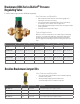

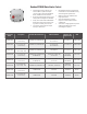
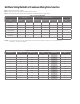
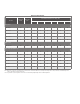


Sizing Method for Braukmann DS06 PRV Selection
Pressure
Regulator
Valve Size
Reduced
Pressure Falloff
(PSI)
Pressure Differential Between Inlet and Outlet
25 psi
50 psi 75 psi 100 psi
Flow Capacity (US gpm) Flow Capacity (US gpm) Flow Capacity (US gpm) Flow Capacity (US gpm)
1/2”
6 7.26 8.15 7.44 6.47
10 10.7 10.66 9.69 8.85
15 14.27 15.72 14.49 13.96
20 17.74 19.59 18.98 18.1
3/4”
6 11.98 14.44 14.53 14.97
10 17.17 21.05 25.23 26.33
15 19.86 25.14 29.32 32.85
20 21.27 26.42 30.42 33.82
1”
6 11.18 11.23 9.51 9.11
10 18.01 18.98 17.39 16.78
15 25.67 28.14 28.71 26.9
20 30.69 34.7 36.19 35.05
1-1/4”
6 7.53 6.34 7.26 7.13
10 20.25 17.88 15.15 14
15 33.02 34.87 32.63 29.68
20 40.07 44.29 46.01 34.61
1-1/2”
6 29.81 32.27 30.87 26.81
10 46.14 50.02 49.89 47.82
15 66.22 78.42 86.74 84.14
20 77.14 92.29 103.82 109.68
2”
6 27.34 25.8 24.48 18.01
10 64.81 97.61 78.15 90.09
15 82.82 105.14 119.94 129.62
20 87.66 107.83 120.95 132.09
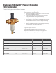
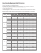
Control water pressure without a gauge
The suitability of a given regulator size is dependent on the pressure requirements where it will operate. For the pressure
regulator valve size required for a specic installation, determine the following:
1. Pressure dierential between inlet and outlet pressure in pounds per square inch (psi),
2. Capacity in gallons per minute, and
3. Allowable reduced pressure fallo in psi. Given these variables, use Table 2 to determine the proper size pressure regulator
valve for your application.
Example: An installation has 135 psi inlet pressure, 60 psi outlet pressure (75 psi pressure dierential). If a 12 gpm capacity is
required with only 10 psi fallo allowable, a 1/2 in. DS06 is required.