
Installation Guide


DCN: 140-02338-01 DRAFT 20619
Page 5
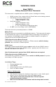
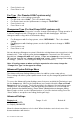
Standard HVAC System
G Fan
W1 Heat Stage 1
Y1 Compressor Stage 1
R 24VAC Return
C 24VAC Common
Thermostat Connection
Y2 Compressor Stage 2
W2 Heat Stage 2
For single transformer systems,
connect R wire to either RC or RH
terminal. They are jumpered
together by the factory installed
jumper.
For systems with separate heating
& cooling transformers, connect
Heating R to RH and Cooling R to
RC. NOTE! REMOVE THE
FACTORY INSTALLED RC/RH
JUMPER.
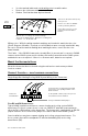
Standard Gas/Electric HVAC System Wiring
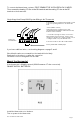
Thermostat Setup:
Standard Gas/Electric HVAC Systems
For Single Stage Heat/Cool Systems:
Go to the Menu screen by pressing and holding the FAN button for 5 seconds
Press the down arrow to select the SYSTEM menu and press Select.
Set the following:
SYSTEM TYPE: Set to STANDARD
FAN TYPE: Set to GAS for typical gas furnace (fan is controlled by the furnace)
Set to ELECTRIC for electric heat (fan on with heat call)
For Two Stage Heat/Cool Systems:
Go to ADVANCED SYSTEMS SETTINGS menu.
From the Setup menu screen, press and hold the Fan and Down arrow buttons
for 5 seconds. Use the Down arrow button to select the following:
2ND
STAGE HEAT ENABLE: Enable second stage heating output
If a single stage heating system, leave this set to N
If a 2 stage heating system, set to Y to enable.
2ND STAGE COOL ENABLE: Enable second stage cooling output
If a single stage cooling system, leave this set to N.
If a two stage cooling system, set to Y to enable.
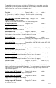
Default Thermostat Setup:
Type: Standard HVAC
Fan Type: Gas Heat
1 Stage heating
1 Stage cooling
No Setup change required
for this configuration
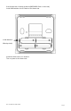
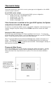
Thermostat back
Typical thermostat wiring colors.
Caution: verify that original wiring
matches. Colors may be different.
Blue
Black/Brown
Red
White
Orange
Yellow
Green
C wire is not required for
battery operation.
C wire is required for 24VAC
operation.
W2/O
W1
24RH
24C
24RC
G
Y1
Y2
Factory Installed RC/RH jumper