User Manual 4CH/8CH/16CH Super HD 4.0MP Network Video Recorder 4.
Getting Started 2 Thank you for purchasing the Reolink Network Video Surveillance(4CH/8CH/16CH) Product. For the latest User Manual, Product Updates and more information about the products, please visit our website at: https://reolink.com/ CAUTION RISK OF ELECTRIC SHOCK DO NOT OPEN CAUTION: TO REDUCE THE RICK OF ELECTRIC SHOCK DO NOT REMOVE COVER. NO USER SERVICEABLE PARTS INSIDE. REFER SERVICING TO QUALIFIED SERVICE PERSONNEL.
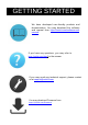
GETTING STARTED We have developed user-friendly products and documentation. You may download the software and manual from https://reolink.com/software-andmanual/ If you have any questions, you may refer to https://reolink.com/faqs/ for the answer. If you may need any technical support, please contact us at support@reolink.com. You may download Firmware from https://reolink.
NOTICES 4 FCC Verification Note: This equipment has been tested and found to comply with the limits for Class B digital device, pursuant to part 15 of the FCC Rules. These limits are designed to provide reasonable protection against harmful interference in a residential installation.
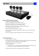
FEATURES 5 Network Video Recorder Features • SUPER HD 4.0 Mega pixel Resolution Real-time Recording at 4.
CONTENTS 6 Gettin g Started…………………… ……………………… ….………………………………… 3 Notic e………..……………………… ……………………….………………………………….. 4 Feature…………………………………………………………...…………………………….5 Contents………………………..…………………… …………….……………………………. 6 Getting Started……………………… ……………………………………………..…………….. 7 NVR Overview ………………………… … … … … … … … … . … … … … … … … … … … . . 8 Connection Diagram …………………………………………………………..………………… 9 Setup W izard ………………………………………………………………….......…………… 12 NVR Software Basic NVR Operation………………… ……………………………………………………..
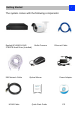
Getting Started 7 The system comes with the following components: Reolink 8CH/16CH NVR 2TB/3TB Hard Drive (Installed) 59ft Network Cable HDMI Cable Bullet Camera Optical Mouse Quick Start Guide Ethernet Cable Power Adapter CD
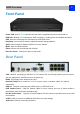
NVR Overview 8 Front Panel Power LED: Solid GREEN indicates that the NVR is supplied with power and turned on. HDD LED: Blinking RED indicates the NVR is writing to / reading from the installed hard drive. USB: Used for connecting the USB mouse or USB Flash drive. Play/Stop: Used to play or stop the selected channel during playback.
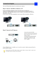
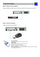
Connection Diagram 9 You can follow below steps to connect your system: Step 1: Connect the NVR to a Monitor or TV Use the HDMI cable (supplied) to connect your NVR to the TV’s HDMI port. .(If there is no display, please connect it to a VGA monitor and change its resolution to 1920*1080). If you need audio output on your TV monitor, the resolution MUST be set to 1920*1080 or 1280*720. Or VGA: Use the VGA cable (supplied) to connect your NVR to the Monitor’s VGA port .
Connection Diagram 10 Step 3: Connect to your network Connect an Ethernet cable from the LAN port on the NVR to LAN port on your router. Step 4: Connect the Mouse Connect the mouse to the USB port. The USB Mouse: •Left click: Selects an item or confirms a choice. •Right click: • Opens the menu bar from the live viewing screen. •Returns one “step” from a submenu. •Opens a context menu in some settings screens.
Connection Diagram 11 Step 5: Connect the Power Adapter Please use the supplied power adapter. For POE NVR device, it is 48 voltage. Camera voltage is 12V only. Please don’t use the NVR 48V power adapter directly to Camera. Otherwise, it will be damaged.
Setup Wizard : Create Password 12 The Setup Wizard will run automatically the first time you start the NVR. The wizard will guide you through all the settings you need to get your NVR up and working, For Security Purpose, Here you need to create the password using at least 6 characters to continue. After Setting, then Click “Next “t o continue. User Name: The NVR’s default account, which is “Admin”. You can’t change the Admin user name.
Setup Wizard : General Configuration 13 General Configuration Language: Choose the language you would like the menu system to display. Video Standard: Choose between NTSC (USA, Canada, Mexico, Japan, Korea and some other regions) or PAL (UK, Europe, Australia and some other areas). If this is set incorrectly, images from your cameras may be distorted, black and white. Resolution: How many pixels the NVR will output.
Setup Wizard : Hard Disc Management 14 Here shows the HDD capacity and free space, if you want to format the HDD, choose the HDD, then click Init or you can click Next to continue. Setup Wizard : Network Configuration This page shows the current network conditions. we will introduce the details on the other chapter. You can click Next to continue.
Setup Wizard : Device list 15 Here you can see the list of cameras that are connected to the NVR. IP Address: Displays the unique IP number and port number that is assigned to the network camera. MAC Address: The Media Access Control address. This is a unique code which cannot be shared - it is hard coded when the camera is manufactured. Name: All camera default name is “Camera1”. Changing its name will help to easily identify the camera. Channel: The channel to which the camera has been assigned.
Setup Wizard : E-mail Configuration 16 E-mail If you want the NVR to send email alerts when alarm events are detected, then you need to configure an outgoing email server for the NVR and choose an email address for it. We recommend creating an account with Gmail specifically for the NVR, and setup its security level to be low. These instructions assume you’re using a Gmail account. Enable SSL or TLS: Check box to enable SMTP Port: The SMTP port of your email server.
Setup Wizard : UID 17 UID: This is the NVR’s Unique Identifier number which will be used later to connect your PC or Smart Phone to the NVR using Reolink P2P Technology. Click Send UID, the UID Number will send to your sender’s E-mail address. You may copy the UID code to Reolink Client for remote access. Setup Wizard : DDNS Configuration DDNS is not required for Reolink P2P remote access. If you intend to access your NVR using older IP technology you will need to configure this service.
Setup Wizard : System Time 18 NTP stands for “Network Time Protocol”. It is a way for the NVR to connect to the Internet and automatically update and maintain the accurate time. There is no requirement to use NTP. It is easy to setup and free to use. Synchronize Every: The interval when the time will SYNC from NTP server. NTP Server: The server you would like to use for NTP. They are all quite comparable in terms of reliability and accuracy. The default NTP server is recommended to use. (pool. ntp.
Basic NVR Operation 19 Using the Live View Screen Live View is the default mode for the NVR. All connected cameras are displayed on-screen. The NVR can display video feeds from up to 4/8/16 cameras depending on the model. Status icon Information on the NVR and camera status is displayed as icons on the Live View screen. Each camera will show its own status icons.
Basic NVR Operation 20 Menu Bar Right click with the mouse on the live view screen to open the Menu Bar Menu: Opens the main menu. Single Camera View: Shows images from one camera in full-screen. Four-Camera View: Divides the screen into four viewing windows, each showing images from one camera. Next Camera(s): Cycles the cameras displayed in viewing mode. Only work for 1/4/8 camera simultaneous live view mode. PIP: Picture-in-Picture.
Basic NVR Operation RLC-411/422 will display as below bar: Zoom In: Optical Zoom in Zoom Out: Optical Zoom out Manually focus far(Only use when AUTO FOCUS has problem) Manually focus near(Only use when AUTO FOCUS has problem) Exit Image Setting: Displays the selected video channel in full screen and shows the Image Settings window for you to change the brightness, contrast, saturation and hue. For more details, see Image Settings in “Display: Camera” Camera Setting: Opens the “Display” menu.
Basic NVR Operation : Manual Record 22 On this page, it shows all the channel Schedule recording is On/Off. if the schedule recording is ON, you can see next to Schedule is a Blue ON Button, and the start and stop is in grey, now you can’t set the manual record. if the schedule recording is OFF, you can see next to Schedule is a RED OFF button, now you can manual set the record start or stop by click the circle dot. Note: This function can only work when the RECORDINGSCHEDULE is disabled.
Main Menu: IP Channel 23 On the IP Channel page, you can • view specific information about cameras • scan for cameras that the NVR is able to detect that are connected to NVR poe ports or under the same router with the NVR. • add cameras to any available channels • delete cameras from their existing channels • • • • • • Name: Shows the name of the camera associated with the channel. IP Address: The IP address assigned to the camera. Channel: The channel number that the camera is connected to.
Main Menu: Display -> Camera 24 On The display: Camera page, you can • Rename the camera • Set the information that will be displayed on-screen • Set where this information will be displayed • Set whether information such as the date will be recorded directly to your videos • Set any areas of the video you want to “mask” • Set the camera video parameters Camera No.: Choose the channel you want to edit here. Camera Name: Shows the name of the camera that’s currently connected to the channel.
Main Menu: Display - > Output 25 On the Display output page, you may set the: • output resolution on screen • the transparency of the menu • the sensitivity of the USB mouse • the boarder of the live view Resolution: The number of “little dots” that make up an image. This should be set as high as possible, but equal to or lower than the maximum resolution your screen/monitor can display. Make sure your monitor supports or exceeds the resolution you choose or it may not be able to display.
Main Menu: Recording - > Encode 26 On Record: Encoding page, you can • choose the resolution (per channel) of recording • change the frame rate (how many images per second the NVR records) • change the data-rate of each video stream. The higher the data rate, the “better” your images will look, but may take up more space in your HDD. Camera No.: Tells the channel you want to set. Encoding Parameters: Tells whether you’re editing the parameters for the mainstream or the substream.
Main Menu: Recording - > Option 27 On the recording: Option page, you may set • Whether the NVR will record a short video before events take place, • how long after events take place the NVR will continue to record • how the NVR will store and divide long recording? • Whether the NVR will continue to record and cover the earliest recording. Overwrite: When enabled, the NVR will record over the files already stored on the hard drive.
Main Menu: Recording - > Schedule 28 On Recording: Schedule Page, you may set the recording time schedule of each channel. There are three types of recording to set: Normal: The NVR will constantly record for any period. You won’t miss anything. Motion: The recommended recording setting for most applications.
Main Menu: Search - > Playback On the Search: Playback page, you can • select the playback channel • choose the video type • Set the start and end time for playback Click Detail button to check the recording type for different time period. You may click on any grid at any time and at channel to start playing. Or you may click Search and see all the file you want to play, then click play button.
Playback Interface 30 The Playback interface is quite similar to a computer’s media player. Most of the controls are quite straight forward and it operates in the same way as a standard media player. Playback Bar: A basic progress meter. You can click to move the current position icon to quickly scan through video events. : sets the output volume of playback. : Used to mark a Start Point and End Point for incident backups. Press and press to mark a start point again to mark an end point.
Main Menu: Search - > Backup On the Search: Backup Page, you should • Connect a USB flash drive to the USB Port on the front panel or at the rear panel of the NVR • Choose the camera(s) you want to backup footage from. • From the Video Type menu, select the type(s) of video you want to backup. • Set your Start Time and End Time. • Select Backup. The backup file list will show you a list of all the video events between the start and end times you have selected.
Main Menu: Search - > Event/Log Search The Event Search menu will show you recordings that were triggered by the NVR when detecting motion. Typically, the majority of recordings based upon “Events” are likely to be recordings triggered by the NVR’s motion detection feature. The search function operates in the same way as the main playback search: the only difference is you’ll select an Event Type rather than a Video Type.
Main Menu: Network - > General 33 On the Network: General Page, you may know the status of your network, like • Network Access • IP Address • Subnet Mask • DNS • Mac Address Network Access: Here you can choose • DHCP: DHCP is a system where one device on your network (usually a router) will automatically assign IP address to device connected to the network.
Main Menu: Network - > Advanced 34 On the Network: Advanced page, you can Set • DDNS • NTP • E-mail • FTP • IP Filter • related media port DDNS: DYNDNS is the only choice. If you do not want to use Reolink UID for access, you may need to apply a DYNDNS account from www.dyndns.com. . NTP: Network Time Protocol. If you’ve got the Camera connected to the Internet, you can have it automatically sync time with an online server.
Network -> Advanced -> DDNS 35 34 DDNS T yp e : choose DynDns. Server Domain Name: Enter the host name that you set up in your DDNS service. This is the address you use to access your network. Username and Password: Enter the username and password you setup with your DDNS server. These do not have to match your username/password combination in either your Camera or router. (for the sake of security, we suggest making them different).
Network -> Advanced -> E-mail Settings 36 35 E-mail Notification tells you what’s going on around your home or business as it happens, then you may configure it to automatically send email alerts as events happen. We suggest using Gmail as your email client. Enable SSL or TSL: Tells whether the email server you’re using requires a secure link. This is on by default, and should be left on if you’re using any of the preset email servers.
Network -> Advanced -> FTP Setting Here you may set the FTP server related information. You should input the ftp server IP address: Port, User Name, Password, so the snapshot or video can directly store to your ftp server. You can set the FTP alarm schedule, you can refer to “Recording: Schedule” on page 28. Check the box after Enable FTP will allow the NVR to do FTP uploading according to the schedule.
Device Setting -> Network Status 38 Here you may find the network information which refers to IP Address / Subnet Mask / Gateway /Preferred DNS /Alternate DNS.
Device Setting -> Alarm -> Motion 39 On Alarm: Motion Page, you may set the motion detection function. What is Motion Detection? Motion Detection is the process of detecting a change in the position of an object relative to its surroundings or a change in the surroundings relative to an object. There are many approaches for motion detection in a continuous video stream.
Device Setting -> Alarm -> Motion Setting You may set the Motion Detection schedule by clicking the Set button next to Schedule. And click and drag in the time grids to setup the alarm periods. Action: Audio Warning: The NVR will use its internal buzzer to beep. Send Email: The NVR will send an auto-email alert when the event type you have selected occurs.
Device Setting -> Alarm -> Exception 41 An Exception is any deviation from the NVR’s normal behavior - phrased another way, it’s like saying the NVR’s been working fine except for these events. There are 4 Exception Type: HDD Full: As the name suggests, this event occurs when the NVR runs out of space on the hard drive to save new footage. This event is redundant if you’ve got overwrite enabled, as the NVR will automatically delete old footage to ensure it can continue to record.
Device -> HDD 42 Here you will find a comprehensive list of hard drives connected to the NVR. External Hard Drive connected via eSATA will be listed here, and be labeled as eSATA. Init.: Initializes the hard drive. You will only need to do this once, assuming that it is not yet initialized. If the Format column reads “No” then choose Init. to initialize the drive. Label: A quick way of differentiating between hard drives.
System -> General On System: General Page, you may: • Set the time and date • Select the language you want for the Menu/GUI. • Set the configuration for automatic adjustment to daylight saving time • easily enable or disable password protection These information has already been set on the Setup Wizard when you first time run the NVR. You may modify from here. System -> User You may add more account username and password.
System -> System Maintain 44 If you’re looking at the System Information screen to check whether you have updated your system to the latest version by the information of BUILD NO.
System -> System Maintain 45 To maintain the NVR, it is suggested that it be rebooted periodically. In much the same way that a computer can become unstable if left on for an extremely long time, the NVR can become unstable too. It is strongly suggested that the NVR be rebooted at least once per week. However, as this can be a hassle, you may set the NVR to reboot itself. Enable auto reboot: Will automatically shut the NVR down and restart it at a certain time.
System -> System Maintain -> Default Setting 46 Default Settings (Restore): Loads the factory default settings. You can choose all or the field you want to set back to default. Configuration (Export): Creates a file containing all the settings you have customized, including your recording preferences, schedule, user-list and so on. It is .tgz file. To export your settings: a) Insert a USB flash drive into the USB port. Ensure it has enough space and it is not writeprotected.
Shut Down You can click Shut down when you want to log out the system. when you click Shut down, it will pop up next windows, click OK to continue. Follow the above same steps to Reboot the device. You can click Lock to Lock the device, but when you want to login again, you need to input the password which you created to login the system.
Warranty 48 Reolink warrants this product against defects in workmanship and material for a period of Two (2) years from its original purchase date. You must present your receipt as proof of purchase for warranty validation. Any unit which proves defective during the stated period will be repaired without charge for parts or labor or replaced at the sole discretion of Reolink. The end user is responsible for all freight charges incurred to send the product to Reolink’s repair center.