
User Manual
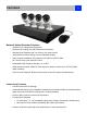

NVR Overview
8
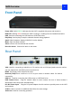
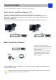
Front Panel
Power LED: Solid GREEN indicates that the NVR is supplied with power and turned on.
HDD LED: Blinking RED indicates the NVR is writing to / reading from the installed hard drive.
USB: Used for connecting the USB mouse or USB Flash drive.
Play/Stop: Used to play or stop the selected channel during playback.
Quad: Switch between display 1/4/9/16 CH on the Monitor
Menu: Open the Menu window
Select: start to use the selected item function
Direction Arrow: Choose the items on the menu.
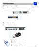
Rear Panel
VGA: Used for connecting a television or PC monitor with a VGA input (make sure the monitor
you use supports the resolution you set in the menu).
HDMI: The primary video output of the NVR.
Network ( LAN) Po r t : connect t h e N V R to your router or network switch for Internet
connectivity.
USB 2.0:Used for connecting the USB mouse or USB Flash Drive.
POE Camera Ports: Plug the network cable for each camera into one of these sockets, it
will transmit video and power simultaneously.
DC 48V Power Input: Plug the DC power adapter into this socket to provide power to the NVR
and cameras
eSATA: Used to connect an additional Hard Drive for extra storage.
Audio Out: Used for connecting speakers.