
Datasheet


78K0/Ix2 CHAPTER 15 SERIAL INTERFACE IICA
R01UH0010EJ0500 Rev.5.00 502
Feb 28, 2012
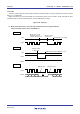
(5) Stop condition detection
INTIICA0 is generated when a stop condition is detected (only when SPIE0 = 1).
15.5.9 Address match detection method
In I
2
C bus mode, the master device can select a particular slave device by transmitting the corresponding slave
address.
Address match can be detected automatically by hardware. An interrupt request (INTIICA0) occurs when a local
address has been set to the slave address register 0 (SVA0) and when the address set to the SVA0 register matches the
slave address sent by the master device, or when an extension code has been received.
15.5.10 Error detection
In I
2
C bus mode, the status of the serial data bus (SDAA0) during data transmission is captured by the IICA shift
register (IICA) of the transmitting device, so the IICA data prior to transmission can be compared with the transmitted IICA
data to enable detection of transmission errors. A transmission error is judged as having occurred when the compared
data values do not match.
15.5.11 Extension code
(1)
When the higher 4 bits of the receive address are either “0000” or “1111”, the extension code reception flag (EXC0)
is set to 1 for extension code reception and an interrupt request (INTIICA0) is issued at the falling edge of the
eighth clock. The local address stored in the slave address register 0 (SVA0) is not affected.
(2) If “111100” is set to the SVA0 register by a 10-bit address transfer and “111100” is transferred from the master
device, the results are as follows. Note that INTIICA0 occurs at the falling edge of the eighth clock.
• Higher four bits of data match: EXC0 = 1
• Seven bits of data match: COI0 = 1
Remark EXC0: Bit 5 of IICA status register 0 (IICAS0)
COI0: Bit 4 of IICA status register 0 (IICAS0)
(3) Since the processing after the interrupt request occurs differs according to the data that follows the extension code,
such processing is performed by software.
If the extension code is received while a slave device is operating, then the slave device is participating in
communication even if its address does not match.
For example, after the extension code is received, if you do not wish to operate the target device as a slave device,
set bit 6 (LREL0) of the IICA control register 0 (IICACTL0) to 1 to set the standby mode for the next communication
operation.
Table 15-3. Bit Definitions of Main Extension Code
Slave Address R/W Bit Description
0 0 0 0 0 0 0 0 General call address
1 1 1 1 0 x x 0 10-bit slave address specification (for address authentication)
1 1 1 1 0 x x 1 10-bit slave address specification (for read command issuance
after address match)
Remark For extension codes other than the above, refer to THE I
2
C-BUS SPECIFICATION published by NXP.