TM V.3.20A Integrated Development Environment User’s Manual Rev. 1.
Microsoft, MS-DOS, Windows, and Windows NT are registered trademarks of Microsoft Corporation in the U.S. and other countries. IBM and AT are registered trademarks of International Business Machines Corporation. Intel and Pentium are registered trademarks of Intel Corporation. Adobe, Acrobat, and Acrobat Reader are trademarks of Adobe Systems Incorporated. All other brand and product names are trademarks, registered trademarks or service marks of their respective holders.
Contents 1. Introduction 9 1.1 Operating Environment 9 1.2 Installation Method 10 1.2.1 Executing the Installer 1.2.2 Notes about TM Versions 1.2.3 Compiler and real time OS Combinations 1.2.4 Directories and Files Generated After Installation 1.3 Usage Precautions 10 10 10 11 12 1.3.1 Notes about File Names 12 1.3.2 Notes about Updating of Dependency Relations 12 1.3.3 Notes about Utility Software such as Virus Check Program 12 1.3.4 Notes about Network 12 1.3.5 Notes about Inspector 12 1.3.
.1 Project Bar 41 4.1.1 Overview 41 4.1.2 Buttons 42 4.1.3 Menus 43 4.1.4 Dialog Boxs 44 4.1.4.1 Tools Information Dialog Box............................................................................................ 44 4.1.4.2 Customize Dialog Box........................................................................................................ 47 4.1.4.3 Debug Tool Information Dialog Box.................................................................................. 50 4.1.4.
4.2.3.24 Online Manual .................................................................................................................. 77 4.2.3.25 About Project Editor ......................................................................................................... 78 4.3 Builder 79 4.3.1 Overview 79 4.3.2 Builder Window 79 4.3.3 Functional Description 80 4.3.3.1 To Execute Build ................................................................................................................
Figures Fig. 2-1 Example of Software Development Using the TM ................................................................. 17 Fig. 2-2 Project Name........................................................................................................................... 18 Fig. 2-3 Conceptual Diagram of the TM .............................................................................................. 19 Fig. 2-4 Project Bar ............................................................................
Fig. 4-3 EDITOR TOOL tab ................................................................................................................ 45 Fig. 4-4 APPLICATION tab................................................................................................................. 46 Fig. 4-5 Customize Dialog Box ............................................................................................................ 47 Fig. 4-6 Setting tab ...................................................................
Fig. 4-51 Inspector Startup Buttons...................................................................................................... 84 Fig. 4-52 Specify Detail Conditions Dialog Box.................................................................................. 85 Fig. 4-53 Rearrange Entries.................................................................................................................. 87 Fig. 4-54 [Update] button ....................................................................
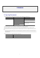
1. Introduction 1.1 Operating Environment The following lists the host computers and OS versions on which TM has been verified to run. Host Computer OS Version Handling instructions IBM PC/AT or compatible Microsoft Windows95 More than Internet Explorer4.0 is being installed. Microsoft Windows98, 98SE Microsoft WindowsMe Microsoft WindowsNT 4.0 Microsoft Windows2000 To install TM, the user have to be granted the administrator privilege. Microsoft WindowsXP Note that the TM does not run on Windows 3.
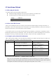
1.2 Installation Method 1.2.1 Executing the Installer To install the TM, execute the installer included with it. z Follow the messages displayed on the screen by the installer as you install the TM. z The following lists the installer programs included with the package: Language Installer name Japanese \TM\W95J\SETUP English \TM\W95E\SETUP 1.2.2 Notes about TM Versions When you are installing the TM over an existing version of TM, the installer displays a message to that effect. To install TM V.3.
1.2.4 Directories and Files Generated After Installation When you finished installing the TM, the directories shown below are created in the directory in which you’ve installed the TM, and the files listed below are copied into these directories. Directory File bin ProjectBar.exe (Project bar execution file) ProjectEditor.exe (Project editor execution file) Builder.exe (Builder execution file) Inspector.exe (Inspector execution file) Server.exe (Communication server execution file) Make.
1.3 Usage Precautions 1.3.1 Notes about File Names The source program file names and work directory names are subject to the following limitations: z No directory or file names that include kanji (2-byte characters) can be used. z Only one instance of the period (.) can be used in a file name. z No network path names can be used. Assign the directory you use to a drive name. z No shortcuts can be used. z No directory or file names that include a space character can be used.
1.3.6 Makefile of library source. A project can’t make it normally when makefile.dos of the compiler accessory is read with TM. Carry out Make in accordance with User’s Manual of the compiler from the Dos window when you change standard input and output library. 1.3.7 The TM project of the former version was taken over.
2) When 16 was specified in the message size or designation was omitted. Compilation option : -Dfar_msg=1 isn’t specified. Link library : mr30.lib and c30mr.lib are specified. system { : message_size = 16; : }; 3) 4) 5) When you put the source file of C besides “Working Directory” (.\). Compilation option : -I. When you put the assembler source file besides “Working Directory” (.\). Assembly option : -I. When you specify the output destination of the objects besides “Working Directory” (.\).
3) When 16 was specified in the message size or designation was omitted, and STANDARD was specified in the interruption prohibition model or designation was omitted. Compilation option : -Dfar_msg=1 isn’t specified, and –fMJI is specified. Link library : mr79sm.lib and c79mrsm.lib are specified. system { : message_size = 16; interrupt_model = STANDARD; : }; 4) When 16 was specified in the message size and or designation was omitted, and SHORT was specified in the interruption prohibition.
3) When 24 was specified in the message size and SHORT was specified in the interruption prohibition model. Compilation option : -Dfar_msg=1 is specified. Link library : mr77lmi.lib and c77mrlm.lib are specified. system { : message_size = 24; interrupt_model = SHORT; : }; 4) When 16 was specified in the message size or designation was omitted, and STANDARD was specified in the interruption prohibition model or designation was omitted. Compilation option : -Dfar_msg=1 isn’t specified.
2. Overview 2.1 Integrated Development Environment The Integrated Development Environment, TM, has been devised to increase the efficiency of software development by integrating various tools such as the compiler, assembler, debugger, and editor into a common Graphical User Interface (GUI).
2.2 Concept of a Project The TM manages the software development process using the concept of a project. Following are managed as part of a project by the TM: z Procedural information necessary to generate the final object (normally the executable object) z Information on source files associated with development z Information on compile, etc. options z Information on development members z Information on development-related documents You specify these items of information as you define a project.
2.3 Roles of Each Tool Working under the TM The TM works in close cooperation with many tools. Some of these tools have GUI as WindowsTM programs, and others such as the C compiler or assembler or the GNU Make command operate at the back end of the TM. The diagram below schematically shows the primary tools controlled by the TM.
■ Project Editor Use the Project Editor to define or alter the source files, compile options, or generation procedure included in a project. The Project Editor works as an editor for the “makefile” handled by the GNU Make command.4 Fig. 2-5 Project Editor ■ Builder The Builder invokes the GNU Make command to build a project based on the “makefile (TMK file)” created by the Project Editor. Fig.
■ Inspector The Inspector provides a facility that based on the debug information included in the “absolute object file” generated by build, analyzes the locations where functions and variables are defined or referenced. Unlike a simple string search, the Inspector does the search based on the information embedded by the compiler.
Those included with the compiler package ■ Compiler and Assembler TM V.3.20A currently supports the following compilers available from Renesas6: z NC30WA V4.00 Release 1 or later z NC308WA V3.00 Release 1 or later z NC79WA V4.00 Release 1 or later z CC32R V.3.00 Release1 or later z NC77WA V.5.20 Release4 or later z SRA74 V.4.10 Release1 or later For the Inspector function to be used, add the “-finfo” option before compiling/assembling the source files.
■ STK Viewer Use the STK Viewer to examine the amount of stack.7 Fig. 2-9 STK Viewer Others ■ Editor Any editor available on the market and you are accustomed to may be used after registering it to the TM. ■ Debugger In addition to the PDxx series debuggers available from Renesas, any third-party debugger may be used after registering it to the TM. 7 The STK Viewer is included in the package as a JavaTM application. For this reason, JavaTM 2 Runtime Environment (JRETM) is used.
2.4 Directory Configuration This section describes how to configure the directory structure of the program when using the TM. When thinking of the directory structure, it is important to understand the exact meaning of the “working directory” and the form in which the source files registered to the project are entered “internally” in the system. Working Directory When generating a project, the Project Editor asks you to specify a working directory.
Example of a directory structure With the above concept taken into account, a directory structure like the one shown below may be conceived.
3. Quick Tour 3.1 Starting the TM and Registering the Editor Used When the TM has been installed normally, the TM can be started by selecting [Start] -> [Programs] -> [RENESASTOOL] -> [TM V.3.xx] -> [TM] from the Start menu. When the TM starts up, the Project Bar appears. Fig. 3-1 Project Bar in Floating State When started for the first time, the Project Bar is in a “floating” state. Grasp this window and bring it to the top of the screen, and you can have it located at the uppermost part of the desktop.
Choose [EDIT TOOL]. In the example below, the Peggy editor from Anchor Systems is registered.10 Fig. 3-4 Registering an Editor The TM does not have any particular editor internally. The editor is a most frequently used tool for program developers. To use an editor the program developers each know well and are accustomed to is we think the most efficient. The TM allows any editor available on the market to be registered for use in it.
3.2 Creating a Project There are following three methods to create a project: z Create a new project z Read a project file of TM V2 or earlier version (MTM file) and convert it into TM V3 format project files z Read an existing makefile and add additional information to create a project Because the TM can read in existing makefiles, a project can easily be created even when you are conventionally not using the TM.12 In this quick tour, we explain the method for creating a new project.
Choose the target chip and set a project name and the working directory. Fig. 3-7 New Project Wizard (Step 2) Next, choose the type of project. Fig.
Choose [A default startup program is used.] for the startup program, and the startup program that comes standard with the compiler is copied into the working directory. Fig. 3-9 New Project Wizard (Step Finish) Click [Finish] on the above dialog box, and the basic project information is created. Registering files When the TM has finished creating initial project information, the Project Editor window appears. Fig.
executed. If main.r30 is created from main.c, for example, write a statement as shown below. main.r30 : main.c nc30 -c main.c In such a case, display on the Project Editor should appear like the one shown below. Show command information on a selected file (item) on the right side of the window. The information will be displayed as shown above. What is meant by this is that main.r30 is created from main.c by an operation “$(CC)$(CFLAGS) main.c.” Now, we’ll show an example of a simple project. Fig.
Now, we’ll try adding a file to the project. Choose the final object and then [Add file] from the right-click menu. Fig. 3-12 Adding a File Choose the file to add. Fig. 3-13 Selecting a Source File Before you can create the final object file “ModelA.x30,” you must have “main.r30” registered in your project. The TM knows the dependency relationship between “.C” files and the “.R30”15. When you register a “.C” file by making use of this, the file is registered reflecting the relationship between “.
In this example, when you register “main.c,” the TM registers “main.r30” simultaneously with it, producing the following display. Fig. 3-14 View after Registering Source Files When you register the source files, be sure to choose basically the final object (absolute object). The file may be registered for other items. In such a case, consider the relationship between target and dependencies in the “makefile” of the GNU make command as you work on file registration.
Definitions of the following are entered by default for each option, respectively: Compiler (nc30) CFLAGS Assembler (as30) AFLAGS Linker (ln30) LFLAGS Load module converter (lmc30) LMCFLAGS “CFLAGS” is a makefile macro, which defines the options used when compiling a program. Choose “CFLAGS” and press the [Mod] button, and the dialog box shown below appears. Fig. 3-17 Option Setup Dialog Box Use this dialog box to choose the options you want to choose.
Or when you want to use different compile options for each file, choose “nc30” press the [New] button. This creates a new macro named “CFLAGS1.” Choose options for this new macro and then the file for which you want the macro to be applied. In this way, you can use different options for each file. Choose the file for which to apply the macro Choose the file for which to apply the macro Fig.
Registering documents Specifications and other documents can be registered.18 To register documents, use the [Add Document] button. Fig. 3-21 Button for Adding Documents For example, when you register development members and documents, the registered information can be displayed on a project view as shown below. Also, you can send a mail to a member or open a document by double-clicking on it. Fig.
3.3 Building a Project The Project Editor is an editor. Therefore, if the project has been changed, it must be saved before building. To save a project, press the [Save] button on the Project Editor. Fig. 3-23 Save Button Next, press the [Build] button on the Project Bar. Fig. 3-24 Build Button This invokes the Builder, and the Builder starts building the project. If you attempted to build a project without saving it, the Project Editor prompts you to save. Fig.
Analyzing with the Inspector The Inspector allows for static program analysis by reading into it the final object “ModelA.x30” that has been built. Use one of the Project Bar buttons shown below to start the Inspector. Detail Setup button Variable Reference Display button Variable Definition Display button Function Reference Display button Function Definition Display button String box Fig.
Fig. 3-30 Showing Variable References In this example, system_code is used in five locations. The variable can be previewed in the window located below by selecting one instance of system_code. (The variable cannot be edited in this window. Double-click the variable location you want to select, and the editor starts up.) The square boxes on the left side of the list are check boxes which can be used in place of a memo. The basic method to use the Inspector is by Copy & Paste.
Fig. 3-32 Showing Function References Starting the debugger The Debugger can be started from the Project Bar. However, before the Debugger can be started in this way, it must be registered to the project concerned. Press the [Tool Register] button, and a dialog box like the one shown below appears. Fig. 3-33 Registering the Debugger Choose the Debugger to use from this dialog box by checking it. When you are using the PD Debugger available from Renesas, choices to select are listed.
4. Reference Manual 4.1 Project Bar 4.1.1 Overview The Project Bar plays the central role of the TM. It accomplishes a linked invocation of each tool. To start the TM, start the Project Bar. To exit the TM, close the Project Bar.
4.1.2 Buttons The following explains the function of each button on the Project Bar. Button Name Function Project Name Display Box Shows a project name. New Project Button Creates a new project. Click this button, and the Project Editor starts and a New Project Wizard opens. Project Open Button Opens a project file. When you specify a project created by an earlier version of the TM or makefile, the Project Editor starts and converts it into the project file useful for this version of the TM.
4.1.3 Menus Shortcut menus are provided for the operations to be performed from the Project Bar. The shortcut menus are listed below. Menu Item Function Change Button Position (B)... Set (C) Always on Top Auto Hide Load Project Changes settings to show, hide, or order of display of each button on the Project Bar. Shows the Project Bar always in front of all other windows. Automatically hides the Project Bar when it is docked to the edge of the screen.
4.1.4 Dialog Boxs 4.1.4.1 Tools Information Dialog Box The Tools Information dialog box is provided for registering a debugger, editor, or application. Fig. 4-1 Tools Information Dialog Box From this dialog box, the following can be set: z To register a debugger... z To register an editor... z To register an application... ■ DEBUG TOOL EDIT TOOL tab APPLICATION DEBUG TOOL tab Use the DEBUG TOOL tab to register a debugger and select the debugger that starts up when you press the debug button.
Debugger List Shows registered debuggers. The user-registered debuggers are shown as “user:xxxx.” The debugger which has its check box checked is the debugger used in the current project. The debugger to use can be changed by clicking the check box of another debugger. Add button Adds a debugger. Clicking this button opens the Debug Tool Information dialog box. Delete button Deletes a selected debugger from the debugger list. However, this button can delete only the user-registered debuggers.
■ APPLICATION tab Use the APPLICATION tab to register an application and select the editor to use in the TM. A button for starting the registered application is added to the Project Bar. Fig. 4-4 APPLICATION tab Application list Shows registered applications. Add button Adds an application. Clicking this button opens the Application Information dialog box. Delete button Deletes a selected application from the application list.
4.1.4.2 Customize Dialog Box The Customize dialog box is provided for changing various settings of the Project Bar. Fig. 4-5 Customize Dialog Box From this dialog box, the following can be set: z To show the Project Bar... z To change buttons... z For Inspector-related settings... ■ Setting tab Button tab Inspector tab Setting tab Use the Setting tab to set the behavior of the Project Bar. Fig.
■ Button tab Use the Button tab to show or hide each button on the Project Bar and change the order in which they are displayed. Fig. 4-7 Button tab Button display view Check the check box of a button, and the button is displayed. Uncheck a button, and the button goes out. Upper button Moves the selected button on the list view one place forward. Lower button Moves the selected button on the list view one place backward. Add Application button Adds an application.
■ Inspector tab Use the Inspector tab to set Inspector-related settings. Fig. 4-8 Inspector tab Auto Read from Clipboard Selects whether or not to automatically copy a copied string from the clipboard into the Inspector’s search string display box.
4.1.4.3 Debug Tool Information Dialog Box The Debug Tool Information dialog box is provided for registering a debugger. Fig. 4-9 Debug Tool Information Dialog Box ■ Name (essential) Enter a debugger name. ■ File Path (essential) Enter a path to the debugger’s execution file. The file can also be selected by clicking the Browse button. ■ Current button The current directory from which to start the debugger can be specified.
4.1.4.4 Edit Tool Information Dialog Box The Edit Tool Information dialog box is provided for registering an editor. Fig. 4-10 Edit Tool Information Dialog Box ■ Name (essential) Enter an editor name. ■ Default Editor check box Check this check box, and the editor you are registering is registered as the default editor to be used by the TM. When this button is unchecked, the editor is only registered. ■ File Path (essential) Enter a path to the editor’s execution file.
■ Environment This field shows environment variables used by the editor. ■ Add button Click this button when you want to add an environment variable. The Environment Settings dialog box opens. ■ Delete button To delete any environment variable, select it from the list and click the Delete button. ■ Modify button To modify any environment variable, select it from the list and click the Modify button. The Environment Settings dialog box opens.
4.1.4.5 Application Tool Information Dialog Box The Application Tool Information dialog box is provided for registering an application. Fig. 4-11 Application Tool Information Dialog Box ■ Name (essential) Enter an application name. ■ File Path (essential) Enter a path to the application’s execution file. The file can also be selected by clicking the Browse button. ■ Current button The current directory from which to start the application can be specified.
■ Modify button To modify any environment variable, select it from the list and click the Modify button. The Environment Settings dialog box opens. ■ OK button Click the OK button, and the contents you changed are reflected before closing the Application Information dialog box. ■ Cancel button Click the Cancel button, and the Application Information dialog box is closed without reflecting the contents you changed.
4.1.4.6 Current Directory Dialog Box The Current Directory dialog box is provided for specifying the runtime directory. Fig. 4-12 Current Directory Dialog Box ■ Directory that contains the execution file The directory that contains the execution file of the tool to start is made the current directory. ■ Working Directory The project’s working directory is made the current directory. ■ Other Specify a directory that you want to be the current directory.
4.1.4.7 Environment Settings Dialog Box The Environment Settings dialog box is provided for specifying environment variables. Fig. 4-13 Environment Settings Dialog Box ■ Name (essential) Enter an environment variable name. ■ Value Specify the value of the environment variable. ■ OK button Click the OK button, and the contents you changed are reflected before closing the Environment Settings dialog box.
4.1.4.8 Utility Execute Dialog Box The Utility Execute Dialog Box starts the utility. Fig. 4-14 Utility Execute Dialog Box ■ Parameter Specify the options for the utility. You can also use the Browse button to select the desired file path. ■ Detail For the automatically TM recognized tools, the Detail button is available. When you click on this button, the Option Settings dialog box appears, allowing you to set options. ■ OK Starts the utility. ■ Cancel Cancels starting the utility.
4.1.4.9 Option Settings Dialog Box The Option Settings Dialog Box set a utility’s option. Choose an option you want to specify by checking its check box. If the option requires specifying one or more parameters, a Specify Parameter dialog box is displayed. From this dialog box, specify the necessary parameters. Fig.
4.2 Project Editor 4.2.1 Overview The Project Editor is a window in which you can view and edit a project. Use the Project Editor to define or change the source files or compile options or the project generation procedure included in the project. The Project Editor functions as an editor for makefiles handled by the GNU Make command. 4.2.2 Window Composition The diagram below shows the window composition of the Project Editor.
4.2.2.1 Menus The Project Editor has the following menus available. ■ File menu The File menu has assigned to it the menu commands to load or save a project file or makefile, exit the Project Editor, and perform other file-related operations.
■ Help menu The Help menu has assigned to it the menu commands to show the method for using the Project Editor or its version information. Menu Menu command Function Help (H) Help (H) Shows help for the TM and help for tools used in the project Online Manual (M) Shows an electronic manual for the TM and an electronic manual for tools used in the project About Project Editor(A) Shows the Project Editor’s version information 4.2.2.
4.2.2.4 Generation Procedure View The generation procedure view shows information on project generation procedure (dependency relationship) in tree form. Shown below is an outline diagram of the generation procedure view. Fig. 4-18 Generation Procedure View 4.2.2.5 Item Information View The item view shows detail information about the item selected on the generation procedure view. Shown below is an outline diagram of the item information view. Fig. 4-19 Item Information View 4.2.2.
4.2.2.7 Document View The document view shows information about the documents. Shown below is an outline diagram of the document view. Fig.
4.2.3 Method of Operation 4.2.3.1 Creating a New Project Create a new project. When you choose this menu command, a New Project dialog box appears. The New Project dialog box is a wizardtype dialog box. From this dialog box, set the necessary entries sequentially. Fig. 4-22 New Project - Step 1 z z z z From Target chip:, choose the target MCU for which you are creating a project. For Project name:, enter the name of the new project you are creating.
z z Here, choose the type of project. When you finished selecting the type of project, click the [Next (N)] button. New Project - Step Compiler is displayed. Fig. 4-24 New Project - Step Compiler z z z From Compiler package:, choose the compiler you use. An already installed product is automatically displayed in the [Compiler package] text box. Choose a startup program. If you choose [A default startup program is used.], the compiler package’s default startup program is copied to the working directory.
If you selected [ASM Project,] [C Project,] [Library Project,] or [Free Project] for the project type in New Project Step 2, you are brought to New Project Step - Complete. If you selected [Realtime OS + ASM Project] or [Realtime OS + C Project], New Project - Step OS is displayed. In this case, specify the startup program in New Project - Step OS. Fig. 4-25 New Project - Step OS z z z z From Realtime OS:, choose the realtime OS you use.
Fig. 4-26 New Project - Step Finish z When you finished setting all entries on the New Project dialog box, the contents you’ve set are displayed here. If the contents shown here are correct, click the [Finish (F)] button. If incorrect, click the [Back (B)] button and reedit any entries that need to be corrected. 4.2.3.2 Opening a Project Open an existing project file. When you choose this menu command, a dialog box for opening files is displayed. From this dialog box, choose the project file you want.
4.2.3.4 Saving the Project by Specifying a Name Save the project being worked on to another project file by specifying a file name. When you choose this menu command, a Save As dialog box is displayed. Specify any file name and folder in which you want to save the project. Fig. 4-28 Saving the Project File z z z Enter the file name you want. In this case, the extension does not need to be specified.
A history of up to four projects is displayed. 4.2.3.7 Exiting the Application Exit the Project Editor. If the project being worked on has been edited, a message is displayed asking you to confirm whether or not to save. Fig. 4-30 Confirming to save z z z To save the project before closing it, click the [Yes] button. To close the project without saving it, click the [No] button. To cancel closing the project, click the [Cancel] button. 4.2.3.8 Toolbar Show or hide the toolbar.
Fig. 4-32 Adding a File z z z Specify the file name you want. Two or more file names can be specified. (File names can be specified in up to about 2,600 characters assuming that they are indicated with the absolute path.) Even a nonexistent file name can be specified. If the specified file has the same extension as that of the compiler or assembler’s default extension, the file is recognized as a source file and has the compiler or assembler’s execution code automatically added as a command. 4.2.3.
Fig. 4-34 Setting a Command z z z For Command, enter a command. The [Def macro ->] button adds a macro displayed by a macro browser to the command line. The [Dyn macro ->] button adds a special macro defined by make to the command line. Click the button, and a popup menu appears. Fig. 4-35 Popup Menu for Dynamic Macro 4.2.3.13 Open Open an item in its associated application. After specifying a text file from items on the generation procedure view, choose this menu command.
4.2.3.14 Properties Show properties of an item. Choose this menu command when an item on the generation procedure view is selected. A File Properties dialog box is displayed. Fig. 4-36 Item Properties z z Properties are displayed only when an existing file is specified. If necessary, edit Attributes. 4.2.3.15 Partial Build Build an item selected on the generation procedure view. 4.2.3.16 Delete Delete a selected item.
4.2.3.17 Macro Browser Show a macro browser. When you choose this menu command, a Macro Browser dialog box is displayed. Fig. 4-37 Macro Browser z z z z This dialog box shows a list of macros used in the project’s generation procedure. To add a new macro, click the [New] button. An Add Macro dialog box is displayed. The new macro is added below the last line of existing macros. Move it up or down using the arrow keys [Up] or [Down] as necessary.
4.2.3.18 Option Browser Show an option browser. When you choose this menu command, an Option Browser dialog box is displayed. Fig. 4-39 Option Browser z z This dialog box shows a list of options used in the project’s generation procedure. To add a new option, choose the tool name you want to add and click the [New] button. An Option dialog box is displayed. Option names are automatically assigned. When you specify an option for each file, add the option first.
Fig. 4-40 Option Dialog Box z Choose an option you want to specify by checking its check box. If the option requires specifying one or more parameters, a Specify Parameter dialog box is displayed. From this dialog box, specify the necessary parameters. 4.2.3.19 Adding Member Information Add member information to the project. When you choose this menu command, an Add Member dialog box is displayed. Fig. 4-41 Adding Member Information For Name:, specify the name of the information you want to add.
4.2.3.20 Adding a Document Add a document file to the project. When you choose this menu command, an Open File dialog box is displayed. Fig. 4-42 Adding a Document z Specify the document file you want to add to the project. When you choose a registered document file and then execute Open, the file is executed by the application associated with it by Windows. 4.2.3.21 Information Show information on the project being worked on. When you choose this menu command, project properties are displayed. Fig.
Fig. 4-44 Project Properties (Tool Tab) z z This dialog box shows information on the project being worked on. With the Tool tab, you can specify whether or not to use any tool, such as a load module converter, not just normally used tools. To specify to use a tool, check its check box. The checked tool is displayed on the option browser. Change options for the tool as necessary. 4.2.3.22 Scan All Dependencies Update the dependency relationship in generation procedure.
4.2.3.25 About Project Editor Show version information of the Project Editor. When you choose this menu command, a Project Editor Version Information dialog box is displayed. Fig. 4-45 Showing Project Editor Version z This dialog box allows you to verify the version of the Project Editor.
4.3 Builder 4.3.1 Overview Builder is the window which does the practice of build and result indication. An error and warning place are indicated with the mark, and help and text editor can start it. 4.3.2 Builder Window Fig.
4.3.3 Functional Description 4.3.3.1 To Execute Build The build operation can be executed in three ways: Build only the files selected with the Project Editor, build the entire project, or rebuild the entire project. For details on how to run, refer to the description of the Project Bar in earlier sections of this manual. Build Rebuild Partial build Fig. 4-47 Build Execution Buttons 4.3.3.
4.3.3.5 To Examine the Meaning of an Error or Warning Right-click the error or warning line to open a submenu and choose [Search for Help On] from that submenu. Help for the cross tool is invoked, with the error message entered in the keyword text box. Choose a keyword string from the list. Click the [View] button on the dialog box to verify the content of the error message. 4.3.3.6 To Save Build Results The build results can be saved to a file in text format.
4.3.3.9 To Search for an Error or Warning When an error or warning occurs, it can be searched for in the upward or downward direction from the cursor position. You can search by error, by warning, or by error & warning. Furthermore, when the end of the file is reached during search, you can start searching from the beginning of the file again, by setting up environment settings accordingly. Execute one of the following operations to search for an error or warning.
4.3.3.12 To Change Operation Environment Choose [Action] - [Environment] from the menu bar. The Setting tab of the Environment dialog box allows you to set the following. Fig. 4-49 Environment Dialog Box (Setting Tab) z z z Restore window condition The window position is restored next time the Builder starts up. Restore font The display font is restored next time the Builder starts up.
4.4 Inspector 4.4.1 Overview Inspector is the window which indicates function information and variable information. Information on the made object is analyzed statically in the cause. Each information is classified with the tab, and indicated respectively in the list. A file name and a line number are outputted by each information, and it is possible that it opens with text editor. 4.4.2 Inspector Window Menu bar Toolbar List window Preview window Fig. 4-50 Inspector Window 4.4.
4.4.3.1 To Show Information List Click on either "Show function definition", "Show function reference", "Show variable definition ", " Show variable reference " on the project bar. The indication tab of the button which it clicked on becomes active. When a function or variable name are specified with [Insp:] box, a focusing tab is indicated, and only the information which corresponded to the specified name is indicated. The wildcard (* or ?) can be used for this name. 4.4.3.
■ Specifying the type Selectable entries Condition All types, signed int, unsigned int, signed char, unsigned char, Other than function reference signed short, unsigned short, signed long, unsigned long, float, double, void pointer, struct, union, enum, typedef, func, near pointer, far pointer, array, void ■ ■ ■ ■ Specifying the storage class Selectable entries Condition Not specify, global, static, inline Not specify, global, static in file, static in function Function definition, function proto
4.4.4.3 To Check a Check Box If, while a line mark area is displayed and any entry is selected, the focus is located in the list window, the check box for an entry can be checked or unchecked by one of the following operations performed. z Checking from the menu bar Choose [Action] - [Set Line Select Mark] from the menu bar. z Checking from a right-click submenu Right-click the entry to open a submenu and choose [Set Line Select Mark] from that submenu. z Checking directly Check the check box directly.
4.4.4.7 To Reanalyze after Loading the Latest Object If the object or project has been altered, the [Update] button on the toolbar is enabled. Click the [Update] button, and the Inspector loads the latest object and reanalyzes the project under the previous analysis conditions. Fig. 4-54 [Update] button 4.4.5 Preview Window 4.4.5.1 To Search for a String When the focus is located in the preview window, a Search for String dialog box is displayed by one of the following operations.
4.4.6.1 Action Tab Fig. 4-55 Environment Setup Dialog Box (Action Tab) ■ Restore window condition Restores the window position the next time the TM starts. ■ Restore font Restores the display font the next time the TM starts. ■ Auto set line mark Automatically checks line marks when opening the editor from the Inspector.
MEMO 90
TM V.3.20A User’s Manual Rev. 1.