
Technical information


Section 3 Software Specifications when Using the SH72546RFCC, SH72544R, SH72543R, SH72531, and SH72531FCC
Rev. 2.00 Feb. 18, 2009 Page 76 of 94
REJ10J1938-0200
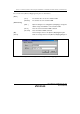
The contents of the [Select Emulation] dialog box are shown below.
[Device] Displays the selected device.
[Change
Emulation in start
up] check box
Displays the [Select Emulation] dialog box when the emulator is activated.
Specifies MD2, MD1, MD0, and FEW and selects the operating mode.
[Select
mode]
The followings are the settings:
mode 0 (CS0 8bit mode): MD2 = 1, MD1 = 1, MD0 = 1, and FEW
= 0
mode 1 (CS0 16bit mode): MD2 = 1, MD1 = 1, MD0 = 1, and FEW
= 1
mode 2 (rom enable): MD2 = 0, MD1 = 0, MD0 = 1, and FEW = 0
mode 3 (single chip): MD2 = 0, MD1 = 0, MD0 = 0, and FEW = 0
[Operating mode]
group box
[User
system
Mode]
Reflects pins set on the user system to MD2, MD1, MD0, and
FEW.
Selects the input clock.
[Emulator
Internal
Clock]
Selects the input clock by moving the level bar.
[Clock] group
box
[User
system
clock]
Specifies the clock set on the user system as the input clock.
Specifies MD_CLKP, MD_CLK1, and MD_CLK0 and selects the clock mode. [Clock Mode]
group box
[Select
Clock
Mode]
The followings are the settings:
mode 0 (PLL x 4, P = EXTAL x 1): MD_CLKP = 0, MD_CLK1 = 0,
and MD_CLK0 = 0
mode 1 (PLL x 6, P = EXTAL x 1): MD_CLKP = 0, MD_CLK1 = 0,
and MD_CLK0 = 1
mode 2 (PLL x 10, P = EXTAL x 1): MD_CLKP = 0, MD_CLK1 =
1, and MD_CLK0 = 0
mode 3 (PLL x 8, P = EXTAL x 1): MD_CLKP = 0, MD_CLK1 = 1,
and MD_CLK0 = 1
mode 4 (PLL x 4, P = EXTAL x 2): MD_CLKP = 1, MD_CLK1 = 0,
and MD_CLK0 = 0