
Technical information


Section 3 Software Specifications when Using the SH72546RFCC, SH72544R, SH72543R, SH72531, and SH72531FCC
Rev. 2.00 Feb. 18, 2009 Page 61 of 94
REJ10J1938-0200
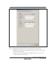
The EVA AUD trace acquisition mode is set in the [Trace buffer full] group box.
[Trace buffer full]
[Trace continue] Selects the continued tracing mode.
[Trace stop] Selects the stop tracing mode.
[Break] Selects the break mode.
The other two items to be selected are the amount of trace data to be acquired by the host
computer from the hardware of the EVA AUD unit and the range of lines to be displayed in the
[EVA AUD] window.
The fast display of the results of EVA AUD tracing is possible with an appropriate setting for that
amount of trace data and is constricted by the setting for lines to be displayed.
This function can be set in the [Display and analyze range] group box.
[Display and analyze range]
[Trace buffer size] Selects the amount of trace data to be
acquired by the host computer from the
hardware of the EVA AUD unit. The amount
of trace data is set in the range from H’2 to
H’40000.
[Start point] The results of tracing are displayed from the
specified line.*
After trace acquisition, the oldest line of trace
data in the display is that at the side of [Start
point]. When the setting for [Trace buffer size]
is changed and [EVA AUD trace acquisition]
is then closed and reopened, the old line of
trace data will change.
[End point] The results of tracing are displayed from the
specified line.*
Note: The interval between [Start point] and [End point] must be less than 524288 lines; e.g.,
when D’0 is set for [End point], the upper limit on [Start point] will be D’524287.
If the EVA AUD trace function is used, select the [EVA AUD trace] check box in the [EVA AUD
trace acquisition] dialog box.