
User`s manual


13
When a one-byte memory is read from the command-line window, the stopping time will be
about 35 ms.
7. Memory Access during User Program Break
The emulator can download the program for the flash memory area (refer to section 6.22,
Download Function to the Flash Memory Area, in the Debugger Part of the SuperH
TM
Family
E10A Emulator User’s Manual). Other memory write operations are enabled for the RAM
area. Therefore, an operation such as memory write or BREAKPOINT should be set only for
the RAM area. When the memory area can be written by the MMU, do not perform memory
write, BREAKPOINT, or downloading.
8. Cache Operation during User Program Break
When cache is enabled, the emulator accesses the memory by the following methods:
•
At memory write: Writes through the cache, then writes to the memory.
•
At memory read: Does not change the cache write mode that has been set.
Therefore, when memory read or write is performed during user program break, the cache state
will be changed.
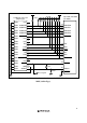
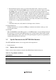
9. Ports E, F, G, and H
The AUD and H-UDI pins are multiplexed as shown in table 2.2.
Table 2.2 Multiplexed Functions
Port Function 1 Function 2
E PTE0 input/output (port) TDO (H-UDI)
E PTE7 input/output (port)* /AUDSYNC output
F PTF7 input (port) / PINT15 input (INTC) /TRST (AUD and H-UDI)
F PTF6 input (port) / PINT14 input (INTC) TMS (H-UDI)
F PTF5 input (port) / PINT13 input (INTC) TDI (H-UDI)
F PTF4 input (port) / PINT12 input (INTC) TCK (H-UDI)
G PTG6 input (port) /ASEMD0 (AUD and H-UDI)
G PTG5 input (port) /ASEBRKAK (H-UDI)
G PTG3 input (port)* AUDATA3 (AUD)
G PTG2 input (port)* AUDATA2 (AUD)
G PTG1 input (port)* AUDATA1 (AUD)
G PTG0 input (port)* AUDATA0 (AUD)
H PTH6 input (port)* AUDCK (AUD)
Note: Note that function 1 cannot be used when the emulator is used. Function 1 can be used
when the AUD pins are not connected to the emulator.