
User`s manual


10
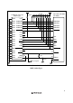
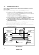
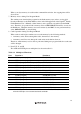
1.5.2 Recommended Circuit (14-Pin Type)
Figure 1.5 shows a recommended circuit for connection between the H-UDI port connector (14
pins) and the MPU.
Notes: 1. Do not connect anything to the N.C. pins of the H-UDI port connector.
2.
Note that the processing of the /ASEMD0 pin differs depending on whether the
emulator is used or not. In addition, the /ASEMD0 pin must be switched on the board
because it is not controlled by the emulator.
(1) When the emulator is used: /ASEMD0 = low (ASE mode)
(2) When the emulator is not used: /ASEMD0 = high (normal mode)
3.
The reset signal in the user system is input to the /RESETP pin of the MCU. Connect
this signal to the H-UDI port connector as the output from the user system.
4.
When a network resistance is used for pull-up, it may be affected by a noise. Separate
TCK from other resistances.
5.
The pattern between the H-UDI connector and the MPU must be as short as possible.
Do not connect the signal lines to other components on the board.
6.
The resistance values shown in figure 1.5 are recommended.
7.
For the pin processing in cases where the emulator is not used, refer to the hardware
manual of the related device.
SH7729R, SH7709S
(FP-208C)
Reset signal
1
TCK
TMS
N.C.
RESET
TDI
TDO
TRST
ASEBRKAK
GND
GND
GND
GND
GND
GND
2
3
4
5
6
7
ASEMD0
8
9
11
10
12
13
14
120
136
128
137
138
193
127
TCK
RESETP
TMS
TDO
TDI
139
3.3 V
4.7 kΩ
3.3 V
4.7 kΩ
H-UDI port connector
(14-pin type)
TRST
ASEBRKAK
Figure 1.5 Recommended Circuit for Connection between the H-UDI Port Connector and
MPU (14-Pin Type)