
User`s manual


19
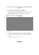
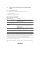
9. Multiplexing the AUD Pins
The AUD pin is multiplexed as shown in table 2.5.
Table 2.5 Multiplexed Functions
Function 1 Function 2
PF2/TCLKD/SCK7* AUDCK
PF3* _AUDSYNC
PF4* AUDATA0
PF5* AUDATA1
PF6* AUDATA2
PF7* AUDATA3
Note: Function 1 can be used when the AUD pins of the device are not connected to the emulator.
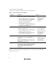
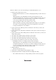
The AUD pins are multiplexed with other pins. The AUD function cannot be used for the
initial values because they are used as other functions. To use the initial value as the AUD
function, set the AUD pins to be used from [AUD pin select] of the [Configuration] dialog box.
The emulator rewrites the registers for the pin function controller (PFC) to enable the specified
AUD pins before executing the user program. When those registers are changed by the user
program, note that the settings of the AUD pins will not be changed.
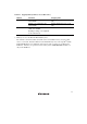
Table 2.6 shows the bits and the values corresponding to the AUD function.
Table 2.6 Registers and Values Set for the AUD Function
Pin Name of the
Port Function
AUD Function
Register and Bit to
be Set
Value to be Set
PF2 AUDCK PFCR1[9:8] 2’b01
PF3 _AUDSYNC PFCR1[12] 1’b1
PF4 AUDATA0 PFCR2[1:0] 2’b01
PF5 AUDATA1 PFCR2[5:4] 2’b01
PF6 AUDATA2 PFCR2[9:8] 2’b01
PF7 AUDATA3 PFCR2[12] 1’b1
10. Using WDT
The WDT does not operate during break.