
User`s manual


10
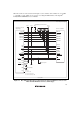
1.5.2 Recommended Circuit (14-Pin Type)
Figure 1.6 shows a recommended circuit for connection between the H-UDI port connector (14
pins) and the MCU when the emulator is in use.
Notes: 1. Do not connect anything to the N.C. pins of the H-UDI port connector.
2. The _ASEMD pin must be 0 when the emulator is connected and 1 when the emulator
is not connected, respectively.
(1) When the emulator is used: _ASEMD = 0
(2) When the emulator is not used: _ASEMD = 1
Figure 1.6 shows an example of circuits that allow the _ASEMD pin to be GND (0)
whenever the emulator is connected by using the user system interface cable.
When the _ASEMD pin is changed by switches, etc., ground pin 9. Do not connect
this pin to the _ASEMD pin.
3. When a network resistance is used for pull-up, it may be affected by a noise. Separate
TCK from other resistances.
4. The pattern between the H-UDI port connector and the MCU must be as short as
possible. Do not connect the signal lines to other components on the board.
5. Since the H-UDI of the MCU operates with the PVcc, supply only the PVcc to the
UVCC pin. Make the emulator’s switch settings so that the user power will be
supplied (SW2 = 1 and SW3 = 1).
6. The resistance value shown in figure 1.6 is for reference.
7. The _TRST pin must be at the low level for a certain period when the power is
supplied whether the H-UDI is used or not.
8. For the pin processing in cases where the emulator is not used, refer to the hardware
manual of the related MCU.