
User`s manual

Section 3 Software Specifications when Using the SH7286, SH7285, and SH7243
Rev. 3.00 Oct. 17, 2008 Page 37 of 66
REJ10J1662-0300
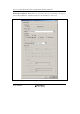
Table 3.8 lists the combinations of conditions that can be set under Ch1 to Ch11 and the software
trace.
Table 3.8 Dialog Boxes for Setting Event Conditions
Function
Dialog Box
Address Bus
Condition
(Address)
Data Bus
Condition
(Data)
Bus State
Condition
(Bus Status)
Count
Condition
(Count)
Action
[Event
Condition 1]
Ch1 O O O O O
(B, T1, and P)
[Event
Condition 2]
Ch2 O O O X O
(B, T1, and P)
[Event
Condition 3]
Ch3 O X X X O
(B and T2)
[Event
Condition 4]
Ch4 O X X X O
(B and T3)
[Event
Condition 5]
Ch5 O X X X O
(B and T3)
[Event
Condition 6]
Ch6 O X X X O
(B and T2)
[Event
Condition 7]
Ch7 O X X X O
(B and T2)
[Event
Condition 8]
Ch8 O X X X O
(B and T2)
[Event
Condition 9]
Ch9 O X X X O
(B and T2)
[Event
Condition 10]
Ch10 O X X X O
(B and T2)
[Event
Condition 11]
Ch11 O
(reset point)
X X X X
Notes: 1. O: Can be set in the dialog box.
X: Cannot be set in the dialog box.
2. For the Action item,
B: Setting a break is enabled.
T1: Setting the trace halt and acquisition conditions are enabled for the internal trace.
T2: Setting the trace halt is enabled for the internal trace.
T3: Setting the trace halt and point-to-point is enabled for the internal trace.
P: Setting a performance-measurement start or end condition is enabled.