
User`s manual


Section 2 Connecting the Emulator to the User System
Rev. 3.00 Oct. 17, 2008 Page 26 of 66
REJ10J1662-0300
2.7 Using the IC Socket to Mount an MCU on the User System
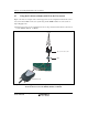
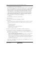
Figure 2.14 shows an example of the external appearance of the configuration when the IC socket
is used to mount an MCU on the user system using and the E200F emulator is connected in on-
chip debugging mode.
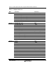
(1) External appearance of the configuration of the on-chip connection when the IC socket is used
for the SH7286, SH7285, or SH7243
H-UDI/AUD probe
User system
MCU
Top cover for IC socket
Screws
Figure 2.14 External Appearance of the Configuration of the On-Chip Connection when
the IC Socket is Used for the SH7286, SH7285, or SH7243