
User`s manual

Section 2 Connecting the Emulator to the User System
Rev. 3.00 Oct. 17, 2008 Page 22 of 66
REJ10J1662-0300
AUDCK
N.C.
TCK
GND
AU DATA 0
GND
AU DATA 1
GND
GND
GND
GND
GND
GND
GND
AU DATA 2
AU DATA 3
UVCC
TMS
GND
N.C.
GND
(GND)
TDI
GND
GND
GND
GND
GND
GND
GND
TDO
1
2
3
4
5
6
7
8
9
10
11
12
13
14
15
16
17
18
19
20
21
22
23
24
25
26
27
28
29
30
31
32
33
34
35
36
_AUDSYNC
_RES
_TRST
_ASEBRKAK
/_ASEBRK
N.C.
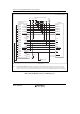
Pin
No.
Signal
Input/
Output
Note
Pin
No.
Signal
Input/
Output
Note
*1
*1
User reset
*2
*2
*3
*4
*2
*2
Input
Input
Input
Input
Output
Output
Output
Output
Output
Output Output
Output
Output
Output
Input/
output
1. Input to or output from the user system.
2. The symbol (_) means that the signal is active-low.
Notes:
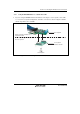
H-UDI port connector
(Pin 1 mark)
(top view)
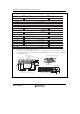
Unit: mm
4.8
M2.6 x 0.45
9.0
0.3
3.9
H-UDI port connector (front view)
3. The emulator monitors the GND signal of the user system and detects whether or not the user system is connected.
4. When the H-UDI/AUD probe is connected to this pin and the ASEMD0# pin is set to 0, do not connect to GND but to
the ASEMD0# pin directly.
: Pattern inhibited area
Edge of the board
(connected to the connector)
0.7
+0.1
0
2
1.27
1
3
4.5
1.1
1.905
9.0
21.59
37.61
43.51
36
35
4
2.8
+0.1
0
φ
4.09
H-UDI port connector (top view)
φ
Figure 2.11 Pin Assignments of the H-UDI Port Connector (36 Pins)