
User`s manual

Section 2 Connecting the Emulator to the User System
Rev. 3.00 Oct. 17, 2008 Page 18 of 66
REJ10J1662-0300
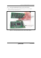
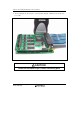
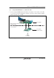
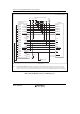
2.2.6 Connecting the EV-chip Unit to the User System Interface Board
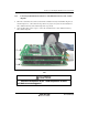
• After checking the location of pin 1, connect the EV-chip unit to the user system interface
board.
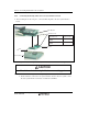
Board
Spacer
User system
EV-chip unit
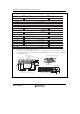
Connector No.
EV-Chip Unit
Connector No.
Board
Connector No.
UCN1
UCN2
User I/F Connector 1
(CN3)
User I/F Connector 2
(CN4)
Figure 2.9 Connecting the User System Interface Board to the EV-chip Unit
CAUTION
Check the orientation of pin 1 before connecting parts.
Notes: 1. Connection of the signals differs depending on the MCU used.
2. For the method to connect the user system interface board to the user system, refer to
the user system interface board user’s manual for each MCU.