
User`s manual

SuperH™ Family E10A-USB Emulator Section 1 Connecting the Emulator with the User System
R20UT2190EJ0100 Rev.1.00 Page 4 of 34
Aug 09, 2012
1.5 Recommended Circuit between the H-UDI Port Connector and the
MPU
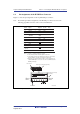
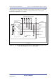
1.5.1 Recommended Circuit (14-Pin Type)
Figure 1.2 shows a recommended circuit for connection between the H-UDI port connector (14
pins) and the MPU when the emulator is in use.
Notes: 1. Do not connect anything to the N.C. pins of the H-UDI port connector.
2. The MPMD pin must be 0 when the emulator is connected and 1 when the emulator is
not connected, respectively.
(1) When the emulator is used: MPMD = 0
(2) When the emulator is not used: MPMD = 1
Figure 1.2 shows an example of circuits that allow the MPMD pin to be GND (0)
whenever the emulator is connected by using the user system interface cable.
When the MPMD pin is changed by switches, etc., ground pin 9. Do not connect this
pin to the MPMD pin.
3. When a network resistance is used for pull-up, it may be affected by a noise. Separate
TCK from other resistances.
4. The pattern between the H-UDI port connector and the MPU must be as short as
possible. Do not connect the signal lines to other components on the board.
5. Supply only the VDDQ voltage to the UVCC pin because the H-UDI of the MPU
operates at the VDDQ voltage (I/O power supply). Make the emulator’s switch settings
so that the user power will be supplied (SW2 = 1 and SW3 = 1).
6. The resistance values shown in figure 1.2 are for reference.
7. For the pin processing in cases where the emulator is not used, refer to the hardware
manual of the related MPU.