
User`s manual

SuperH™ Family E10A-USB Emulator Section 1 Connecting the Emulator with the User System
R20UT2190EJ0100 Rev.1.00 Page 3 of 34
Aug 09, 2012
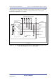
1.4 Pin Assignments of the H-UDI Port Connector
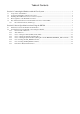
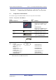
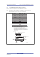
Figure 1.1 shows the pin assignments of the 14-pin H-UDI port connector.
Note: Note that the pin number assignments of the H-UDI port connector shown on the
following page differ from those of the connector manufacturer.
Pin 1 mark
Notes:
1. Input to or output from the user system.
2. The symbol (#) means that the signal is active-low.
3. The emulator monitors the GND signal of the user system and
detects whether or not the user system is connected.
25.0
23.0
6 x 2.54 = 15.24
(2.54)
0.45
Pin 1
Pin 8
Pin 7
Pin 14
Pin 1 mark
H-UDI port connector
(top view)
H-UDI port connect
o
(top view)
Pin No. Signal
1
2
3
4
5
6
7
8
9
11
10, 12,
and 13
14
TCK
TRST#
TDO
ASEBRK#
/ BRKACK
TMS
TDI
RESET#
N.C.
(GND)
UVCC
GND
Input/
Output*
1
*2
*2
GND
*3
Output
Input
Input
Output
Input/
output
Input
Input
Output
Output
SH7766
Pin No.
4.
When the user system interface cable is connected to this pin
and the MPMD pin is set to 0, do not connect to GND but to the
MPMD pin directly.
Note
User reset
*2
*4
Unit: mm
H25
H24
G24
E24
M24
L25
G25
Figure 1.1 Pin Assignments of the H-UDI Port Connector (14 Pins)