
User`s manual

SuperH™ Family E10A-USB Emulator Section 1 Connecting the Emulator with the User System
R20UT2190EJ0100 Rev.1.00 Page 2 of 34
Aug 09, 2012
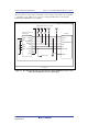
1.2 Connecting the Emulator with the User System
To connect the E10A-USB emulator (hereinafter referred to as the emulator), the H-UDI port
connector must be installed on the user system to connect the user system interface cable. When
designing the user system, refer to an example of recommended connection between the connector
and the MPU shown in this manual. In addition, read the E10A-USB emulator user's manual and
hardware manual for the related device.
Table 1.2 shows the type number of the emulator, the corresponding connector type, and the use of
AUD function.
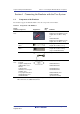
Table 1.2 Type Number, AUD Function, and Connector Type
Type Number Connector AUD Function
HS0005KCU01H, HS0005KCU02H 14-pin connector Not available
The H-UDI port connector has the 14-pin type as described below. Use it according to the
purpose of the usage.
1. 14-pin type (without AUD function)
The AUD trace function cannot be used because only the H-UDI function is supported. Since
the 14-pin type connector is smaller than the 36-pin type (1/2.5), the size of the area where the
connector is installed on the user system can be reduced.
1.3 Installing the H-UDI Port Connector on the User System
Table 1.3 shows the recommended H-UDI port connectors for the emulator.
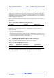
Table 1.3 Recommended H-UDI Port Connectors
Connector Type Number Manufacturer Specifications
14-pin connector 2514-6002 Minnesota Mining &
Manufacturing Ltd.
14-pin straight type
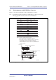
Note: When designing the 14-pin connector layout on the user board, do not place any
components within 3 mm of the H-UDI port connector.