
User`s manual

11
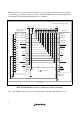
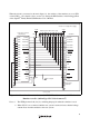
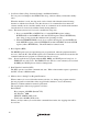
When the circuit is connected as shown in figure 1.5, the switches of the emulator are set as SW2
= 1 and SW3 = 1. For details, refer to section 3.8, Setting the DIP Switches, in the Debugger Part
of the SuperH
TM
Family E10A-USB Emulator User’s Manual.
1
TCK
TMS
RESET
TDI
TDO
TRST
GND
GND
GND
GND
(GND)
2
3
4
5
6
7
9
10
12
13
14
TCK
RES
TMS
TDO
TDI
TRST
VccQ
SH7047F
59
63
58
61
60
87
ASEBRKAK
ASEBRKAK
11
DBGMD
16
UVCC
VccQ
N.C.
8
11
H-UDI port connector
(14-pin type)
Reset signal
Pulled-up at 4.7 k
Ω
or more (all)
User system
VccQ = 5.0 V (I/O power supply)
FWP
83
Jumper pins
switched *
Figure 1.5 Recommended Circuit for Connection between the H-UDI Port Connector and
MCU when the Emulator is in Use (14-Pin Type UVCC Connected)
Note: The FWP pin must be 0 (low) by switching jumper pins when the emulator is used.