
User`s manual

5
Notes:
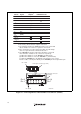
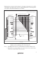
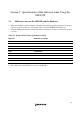
H-UDI port connector
(Pin 1 mark)
(top view)
Unit: mm
4.8
M2.6 x 0.45
9.0
0.3
3.9
H-UDI port connector (front view)
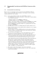
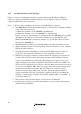
1. Input to or output from the user system.
2. The slash (/) means that the signal is active-low.
3. The emulator monitors the GND signal of the user system and detects whether or not the user system is connected.
4. If the VccQ pin is not connected to the UVCC, the I/O voltage of the user system interface will be fixed to 5.0 V.
5. The /DBGMD pin must be 0 when the emulator is connected and 1 when the emulator is not connected, respectively.
(1) When the emulator is used: /DBGMD = 0 (ASE mode)
(2) When the emulator is not used: /DBGMD = 1 (normal mode)
To allow the /DBGMD pin to be GND by connecting the user system interface cable, connect pin 22 directly to
the /DBGMD pin. Do not ground the pin.
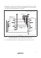
: Pattern inhibited area
Edge of the board
(connected to the connector)
0.7
+0.1
0
φ
2
1.27
1
3
4.5
1.1
1.905
9.0
21.59
37.61
43.51
36
35
4
2.8
+0.2
0
φ
4.09
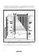
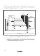
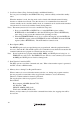
H-UDI port connector (top view)
Pin
No. Signal
Input/
Output
Note
Note
UVCC
TMS
/RES
GND
N.C.
GND
/TRST
GND
TDI
GND
GND
GND
GND
GND
GND
GND
TDO
/ASEBRKAK
I/O
I/O
I/O
I/O
I/O
I/O
Input
Input
Input
Input
Input
Input
Output
Output
Output
Output
Output
1
2
3
4
5
6
7
8
9
10
11
12
13
14
15
16
17
18
19
20
21
22
23
24
25
26
27
28
29
30
31
32
33
34
35
36
Pin
No. Signal
Input/
Output
*1 *1
*2
*2
*2
*2
SH7047F
Pin No.
SH7047F
Pin No.
*3
*5
*4
User reset
AUDCK
AUDRST
AUDMD
TCK
GND
AU DATA 0
GND
AU DATA 1
GND
GND
GND
GND
GND
GND
GND
AU DATA 2
AU DATA 3
/AUDSYNC
92
90
88
86
78
63
79
81
80
59
58
61
60
87
11
Figure 1.1 Pin Assignments of the H-UDI Port Connector (36 Pins)