
User`s manual

SuperH™ Family E10A-USB Emulator Section 1 Connecting the Emulator with the User System
R20UT2163EJ0200 Rev. 2.00 Page 4 of 43
May 23, 2013
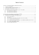
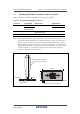
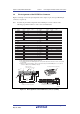
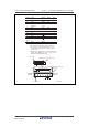
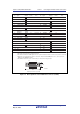
1.4 Pin Assignments of the H-UDI Port Connector
Figures 1.2 through 1.4 show the pin assignments of the 36-pin, 14-pin, and 38-pin H-UDI port
connectors, respectively.
Note: Note that the pin number assignments of the H-UDI port connector shown on the
following pages differ from those of the connector manufacturer.
1. Input to or output from the user system.
2. The symbol (#) means that the signal is active-low.
Notes:
H-UDI port connector
(Pin 1 mark)
(top view)
Unit: mm
4.8
M2.6 x 0.45
9.0
0.3
3.9
H-UDI port connector (front view)
3. The emulator monitors the GND signal of the user system and detects whether or not the user system
is connected.
Pin
No.
Signal
Input/
Output
Note
AUDSYNC
N.C.
N.C.
TCK
GND
AU DATA 0
GND
AU DATA 1
GND
GND
GND
GND
GND
GND
GND
AU DATA 2
AU DATA 3
UVCC
TMS
RESET#
GND
GND
TRST#
(GND)
TDI
GND
GND
GND
GND
GND
GND
GND
TDO
ASEBRK#/
BRKACK
Input
Input
User reset
Input
Input
Output
Input/
output
Output
Output
Output
Output
Output
Output
Output
Output
Output
1
2
3
4
5
6
7
8
9
10
11
12
13
14
15
16
17
18
19
20
21
22
23
24
25
26
27
28
29
30
31
32
33
34
35
36
Pin
No.
Signal
Input/
Output
Note
*1
*1
*2
*4
*2
*2
*3
AUDCK
N.C.
: Pattern inhibited area
Edge of the board
(connected to the connector)
0.7
+0.1
0
2
1.27
1
3
4.5
1.1
1.905
9.0
21.59
37.61
43.51
36
35
4
2.8
+0.1
0
4.09
H-UDI port connector (top view)
SH7752
Pin No.
SH7752
Pin No
.
4. When the user system interface cable is connected to this pin and the MPMD pin is set to 0, do not
connect to GND but to the MPMD pin directly.
H3
J3
J4
H1
H2
G1
C18
B18
B17
D18
C17
K5
F1
Figure 1.2 Pin Assignments of the H-UDI Port Connector (36 Pins)