
User`s manual

SuperH™ Family E10A-USB Emulator Section 1 Connecting the Emulator with the User System
R20UT2163EJ0200 Rev. 2.00 Page 3 of 43
May 23, 2013
1.3 Installing the H-UDI Port Connector on the User System
Table 1.3 shows the recommended H-UDI port connectors for the emulator.
Table 1.3 Recommended H-UDI Port Connectors
Connector Type Number Manufacturer Specifications
DX10M-36S Screw type
36-pin connector
DX10M-36SE,
DX10G1M-36SE
Hirose Electric Co., Ltd.
Lock-pin type
14-pin connector 2514-6002 Minnesota Mining &
Manufacturing Ltd.
14-pin straight type
38-pin connector 2-5767004-2 Tyco Electronics Corporation 38-pin Mictor type
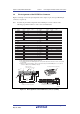
Note: When designing the 36-pin connector layout on the user board, do not connect any
components under the H-UDI connector. When designing the 14-pin connector layout on
the user board, do not place any components within 3 mm of the H-UDI port connector.
When designing the 38-pin connector layout on the user board, reduce cross-talk noise etc.
by keeping other signal lines out of the region where the H-UDI port connector is situated.
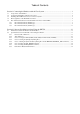
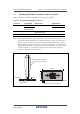
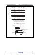
As shown in figure 1.1, an upper limit (5 mm) applies to the heights of components
mounted around the user system connector.
5 mm
2-5767004-2
Target system
E10A-USB optional 38-pin
user system interface cable
H-UDI port connector (top view)
: Area to be kept free of other components
50 mm
20 mm
137
38 2
Figure 1.1 Restriction on Component Mounting