
User`s manual

SuperH Family E10A-USB Emulator for Multi-core Microcomputers Section 7 Tutorial SH-4A
R20UT0363EJ0500 Rev. 5.00 Page 253 of 296
Aug 10, 2012
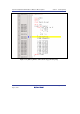
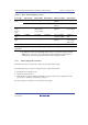
Table 7.3 [Trace Window] Display Contents
Trace Type Type Column BUS Column R/W Column Address Column Data Column
Branch
trace
BRANCH
*1
No display No display Branch source
address
*1
No display
DESTINATION No display No display Branch destination
address
No display
Memory-
range
access
trace
MEMORY Bus through
which access
is proceeding
Read/write Memory access
address
Memory
access data
*1
Software
trace
S_TRACE No display No display Trace(x) function
execution address
Variable x
data
System bus
trace
MEMORY No display Read/write Memory access
address
Memory
access data
(write only)
*1
Data lost
*2
LOST No display No display No display No display
CPU wait
generation
*2
CPU-WAIT No display No display No display No display
Notes: 1. Not displayed when the PPC option is in use.
2. According to the device being debugged, there may be no output for the [Lost] or [CPU-
WAIT] type. In such a case, it is not possible to clarify whether the trace data was not
output in time or the CPU generated a wait state for the output trace data.
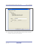
7.20.3 Memory Output Trace Function
This function is used to write the trace result to the specified memory range.
The following is the procedure for setting the memory output trace function.
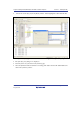
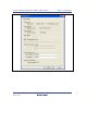
(1) Setting the trace acquisition mode
Display the [Trace] window.
Click the [Trace] window with the right-hand mouse button and select [Acquisition] from the
popup menu to display the [Acquisition] dialog box.
The trace acquisition condition is set in the [Trace mode] page.