
User`s manual

SuperH™ Family E10A-USB Emulator Section 1 Connecting the Emulator with the User System
R20UT2188EJ0100 Rev. 1.00 Page 5 of 24
Aug 09, 2012
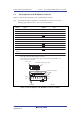
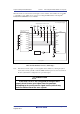
When the circuit is connected as shown in figure 1.2, the switches of the emulator are set as SW2
= 1 and SW3 = 1. For details, refer to section 3.8, Setting the DIP Switches, in the SuperH
TM
Family E10A-USB Emulator User’s Manual.
1
TCK
TMS
RES#
TDI
TDO
TRST#
N.C.
GND
GND
GND
GND
GND
2
3
4
5
6
7
ASEMD
8
9
11
10
12
13
14
TCK
RES#
TMS
TDO
TDI
TRST#
Vcc
Vcc Vcc Vcc
N.C.
MCU
Vcc
Vcc
10 kΩ
UVCC
Vcc
Vcc
100 Ω
All pulled-up at 4.7 kΩ to 10 kΩ
Vcc = I/O power supply
H-UDI port connector
(14-pin type)
Reset circuit
User system
*
Figure 1.2 Recommended Circuit for Connection between the H-UDI Port Connector and
MCU when the Emulator is in Use (14-Pin Type)
Note: If the function for the output of a reset signal from the emulator by selecting the [Reset
assert (Auto Connect)] checkbox when the HEW is linked up is in use, the reset circuit of
the user system must be configured for an open-drain output.
CAUTION
If the reset circuit is not configured for an open-drain
output, do not issue a reset signal from the emulator.
Attempting to do so will cause a signal conflict, which may
lead to a malfunction of the user system.