
User`s manual

SuperH™ Family E10A-USB Emulator Section 1 Connecting the Emulator with the User System
R20UT2188EJ0100 Rev. 1.00 Page 3 of 24
Aug 09, 2012
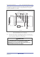
1.4 Pin Assignments of the H-UDI Port Connector
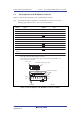
Figure 1.1 shows the pin assignments of the 14-pin H-UDI port connector.
Note: Note that the pin number assignments of the H-UDI port connector shown on the
following pages differ from those of the connector manufacturer.
1
2
3
4
5
6
7
8
9
11
10, 12,
and 13
14
TCK
TRST#
TDO
N.C.
TMS
TDI
RES#
N.C.
GND
UVCC
GND
GND
Pin 1 mark
Notes:
1. Input to or output from the user system.
2. The symbol (#) means that the signal is active-low.
3. The emulator monitors the GND signal of the user system and detects whether or not
the user system is connected.
25.0
23.0
6 x 2.54 = 15.24
(2.54)
0.45
Pin 1
Pin 8
Pin 7
Pin 14
Pin 1 mark
H-UDI port connector
(top view)
H-UDI port connector
(top view)
Unit: mm
Pin No. Signal
Input/
Output*
1
Note
User reset
*2
*2
*3
Input
Input
Output
Input
Input
Output
Output
Output
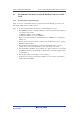
Figure 1.1 Pin Assignments of the H-UDI Port Connector (14 Pins)