
User`s manual

SuperH™ Family E10A-USB Emulator Section 2 Software Specifications when Using the Emulator
R20UT2188EJ0100 Rev. 1.00 Page 11 of 24
Aug 09, 2012
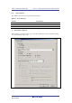
Table 2.6 lists the combinations of conditions that can be set under Ch1 to Ch11.
Table 2.6 Dialog Boxes for Setting Event Conditions
Function
Dialog Box
Address Bus
Condition
(Address)
Data Bus
Condition
(Data)
Bus State
Condition (Bus
Status)
Count
Condition
(Count)
Action
[Event
Condition 1]
Ch1 O O O O O
(B, T1, and P)
[Event
Condition 2]
Ch2 O O O X O
(B, T1, and P)
[Event
Condition 3]
Ch3 O X X X O
(B and T2)
[Event
Condition 4]
Ch4 O X X X O
(B and T3)
[Event
Condition 5]
Ch5 O X X X O
(B and T3)
[Event
Condition 6]
Ch6 O X X X O
(B and T2)
[Event
Condition 7]
Ch7 O X X X O
(B and T2)
[Event
Condition 8]
Ch8 O X X X O
(B and T2)
[Event
Condition 9]
Ch9 O X X X O
(B and T2)
[Event
Condition 10]
Ch10 O X X X O
(B and T2)
[Event
Condition 11]
Ch11 O
(reset point)
X X X X
Notes: 1. O: Can be set in the dialog box.
X: Cannot be set in the dialog box.
2. For the Action item,
B: Setting a break is enabled.
T1: Setting the trace halt and acquisition conditions are enabled for the internal trace.
T2: Setting the trace halt is enabled for the internal trace.
T3: Setting the trace halt and point-to-point is enabled for the internal trace.
P: Setting a performance-measurement start or end condition is enabled.
The [Event Condition 11] dialog box is used to specify the count of [Event Condition 1]
and becomes a reset point when the sequential condition is specified.