
User`s manual

SuperH™ Family E10A-USB Emulator Section 2 Software Specifications when Using the Emulator
R20UT2188EJ0100 Rev. 1.00 Page 7 of 24
Aug 09, 2012
Section 2 Software Specifications when Using the Emulator
2.1 Differences between the SH72A2, SH72A0, and the Emulator
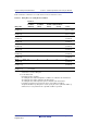
1. When the emulator system is initiated, it initializes the general registers and part of the control
registers as shown in table 2.1. The initial values of the MCU are undefined.
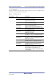
Table 2.1 Register Initial Values at Emulator Link Up
Register Emulator at Link Up
R0 to R14 H'00000000
R15 (SP) Value of the SP in the power-on reset vector table
PC Value of the PC in the power-on reset vector table
SR H'000000F0
GBR H'00000000
VBR H'00000000
TBR H'00000000
MACH H'00000000
MACL H'00000000
PR H'00000000
FPSCR* H'00040001
FPUL* H'00000000
FPR0-15* H'00000000
Note: If the MCU does not incorporate the floating-point unit (FPU), these registers are not
displayed.
Note: When a value of the interrupt mask bit in the SR register is changed in the [Registers]
window, it is actually reflected in that register immediately before execution of the user
program is started. It also applies when the value is changed by the REGISTER_SET
command.
2. The emulator uses the H-UDI; do not access the H-UDI.
3. Low-Power States
⎯ When the emulator is used, the sleep state can be cleared with either the clearing function
or with the [STOP] button, and a break will occur.
⎯ Before stopping the supply of a clock signal to the FPU, be sure to use the command-line
window to prohibit access to the FPU registers. Once this setting is made, H’FF is always
indicated as the read value of each of the FPU registers in the register window, and writing
becomes ineffective. For details, see [Help] -> [Emulator Help] -> [Command Line
Interface] -> [FPU_ACCESS] on the menu bar of the High-performance Embedded
Workshop.
4. Reset Signals
The MCU reset signals are only valid during emulation started with clicking the GO or STEP-
type button. If these signals are enabled on the user system in command input wait state, they
are not sent to the MCU.
Note: Do not break the user program when the /RES signal is being low. A TIMEOUT error
will occur.