
User`s manual

SuperH Family E10A-USB Emulator Section 3 Preparation before Use
R20UT0870EJ1000 Rev. 10.00 Page 42 of 292
Aug 10, 2012
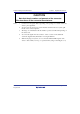
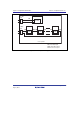
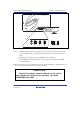
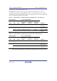
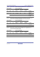
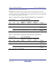
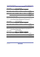
3.9 Interface Circuits in the Emulator
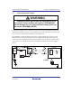
Figures 3.14 through 3.17 show interface circuits in the emulator. Use them as a reference to
determine the value of the pull-up resistance.
Note: The 74LVC2G125 operates at 3.3 V or VCC (1.8 to 5.0 V) from the H-UDI port
connector (changed by the switch).