
User`s manual

SuperH Family E10A-USB Emulator Section 3 Preparation before Use
R20UT0870EJ1000 Rev. 10.00 Page 41 of 292
Aug 10, 2012
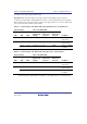
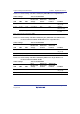
Table 3.10 Switch Settings of the E10A-USB (Using SH-3/SH-4 Series 14-pin Interface)
Switch Settings State of the E10A-USB
SW1
SW2
SW3
User-
interface I/O
Voltage
Signal to be
Connected
to Pin 8
Signal to be
Connected
to Pin 11
Condition
0 (off) - - - - - The emulator is
only set up
1 (on) 0 (off) 1 (on) 3.3 V fixed N.C.
*1
N.C. UVCC is
disconnected
1 (on) 1 (on) 1.8 V to 5.0 V N.C. UVCC Power is supplied
to UVCC
Note: Pin 8 can be connected to GND.
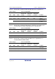
Table 3.11 Switch Settings of the E10A-USB (Using New_SH-Mobile Series/SH-4A Series
Products with 4-bit AUD Bus Width/SH-2A Series 14-pin Interface)
Switch Settings State of the E10A-USB
SW1
SW2
SW3
User-
interface I/O
Voltage
Signal to be
Connected
to Pin 15
Signal to be
Connected
to Pin 29
Condition
0 (off) - - - - - The emulator is
only set up
1 (on) 1 (on) 1 (on) 1.8 V to 5.0 V N.C. UVCC Normally used
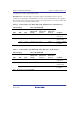
Table 3.12 Switch Settings of the E10A-USB (Using SH-4A Series 14-pin Interface for
Products with 8-bit AUD Bus Width)
Switch Settings State of the E10A-USB
SW1
SW2
SW3
User-
interface I/O
Voltage
Signal to be
Connected
to Pin 15
Signal to be
Connected
to Pin 29
Condition
0 (off) - - - - - The emulator is
only set up
1 (on) 1 (on) 1 (on) 3.3 V fixed N.C. N.C. Normally used