
User`s manual

SuperH Family E10A-USB Emulator Section 3 Preparation before Use
R20UT0870EJ1000 Rev. 10.00 Page 40 of 292
Aug 10, 2012
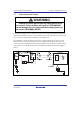
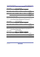
Settings for use of the 14-pin interface cable
Description: When the VCC (I/O power supply related to the H-UDI) of the user system is
connected to the UVCC pin of the H-UDI port connector, set the UVCC with the power supplied.
Here, the I/O voltage of the user interface applies to the ranges between 1.8 V to 5.0 V. If the VCC
is not connected, set the UVCC as disconnected.
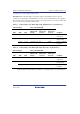
Table 3.8 Switch Settings of the E10A-USB (Using SH-Mobile Series 14-pin Interface)
Switch Settings State of the E10A-USB
SW1
SW2
SW3
User-
interface I/O
Voltage
Signal to be
Connected
to Pin 8
Signal to be
Connected
to Pin 11
Condition
0 (off) - - - - - The emulator is
only set up
1 (on) 0 (off) 0 (off) 3.3 V fixed N.C.
*1
/CA UVCC is
disconnected
1 (on) 1 (on) 1.8 V to 5.0 V /CA UVCC Power is supplied
to UVCC
Note: Pin 8 can be connected to GND.
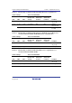
Table 3.9 Switch Settings of the E10A-USB (Using SH-2 Series 14-pin Interface)
Switch Settings State of the E10A-USB
SW1
SW2
SW3
User-
interface I/O
Voltage
Signal to be
Connected
to Pin 8
Signal to be
Connected
to Pin 11
Condition
0 (off) - - - - - The emulator is
only set up
1 (on) 0 (off) 1 (on) 3.3 V fixed N.C.
*1
N.C. UVCC is
disconnected
1 (on) 1 (on) 1.8 V to 5.0 V N.C. UVCC Power is supplied
to UVCC
Note: Pin 8 can be connected to GND.