
User`s manual

SuperH Family E10A-USB Emulator Section 3 Preparation before Use
R20UT0870EJ1000 Rev. 10.00 Page 37 of 292
Aug 10, 2012
ON
OFF
1
0
2
3
1
1
0
2
3
1
ACT
RENESAS
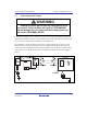
USER I/F
E10A
USB
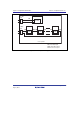
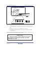
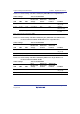
Figure 3.13 DIP Switches
Notes: 1. When the VCC pin (I/O power supply) on the user system is connected to the UVCC
pin, the emulator is able to operate at the same voltage level of the user interface as
VCC.
2. The /CA pin is only supported by the SH-Mobile microcomputers.
3. The /AUDMD pin is only supported by microcomputers with the SH2-series RAM
monitoring function.
Tables 3.3 through 3.8 show the relationships between settings and functions of DIP switches 1 to
3. Use the settings depending on the usage of the user system.
CAUTION
Use only the settings shown in tables 3.3 to 3.8. Use of
other settings will not activate the emulator. The USER
PROGRAM will be LOST.