
User`s manual

SuperH Family E10A-USB Emulator Section 3 Preparation before Use
R20UT0870EJ1000 Rev. 10.00 Page 36 of 292
Aug 10, 2012
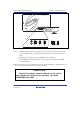
3.8 Setting the DIP Switches
WARNING
Do not change switches (SW2 and SW3) while the
emulator and the user sytem are turned on. The changing of
switches (SW2 and SW3) will result in a FIRE HAZARD and
will damage the user system and the emulator product. The
USER PROGRAM will be LOST.
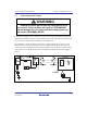
The emulator incorporates a switch (SW1) for setting up the emulator, a switch (SW2) for
determining whether or not UVCC*
1
is connected, and a switch (SW3) for determining which pins
of the H-UDI port connector are assigned to the /CA pin*
2
and the /AUDMD pin*
3
. To change
these settings, use the DIP switches that are attached to the lower right of the emulator's upper
side. To open the sliding switch cover, slide it to the right. The DIP switches consist of three
switches (SW1 to SW3) as shown in figure 3.13. When they are in the upper position, the
emulator is turned on. When they are in the lower position, the emulator is turned off.