
User`s manual

SuperH Family E10A-USB Emulator Section 3 Preparation before Use
R20UT0870EJ1000 Rev. 10.00 Page 33 of 292
Aug 10, 2012
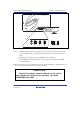
CAUTION
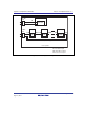
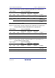
Note that the pin number assignments of the connector
differ from those of the connector manufacturer.
Notes: 1. Connection of the signals differs depending on the package. For details, refer to the
device’s pin assignments.
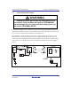
2. To remove the 14-pin type user system interface cable from the user system, pull
the tab on the connector upward.
3. The range of communication that the emulator operates at is different depending on
the device used.
4. To connect the signals from the connector, refer to section 1 in the additional
document, Supplementary Information on Using the SHxxxx.
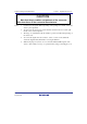
5. When developing user systems, do not connect the TDI and TDO signals of the
device to the boundary scan loop, or separate them by using a switch (figure 3.11).