
User`s manual

SuperH Family E10A-USB Emulator Section 3 Preparation before Use
R20UT0870EJ1000 Rev. 10.00 Page 31 of 292
Aug 10, 2012
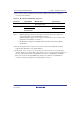
(1) The connector must be installed to the user system. Table 3.2 shows the recommended
connector for the emulator.
Table 3.2 Recommended H-UDI Port Connector
Connector Type Number Manufacturer Specifications
14-pin connector 2514-6002 Minnesota Mining &
Manufacturing Ltd.
14-pin straight type
36-pin connector DX10M-36S Hirose Electric Co., Ltd. Screw type
DX10M-36SE,
DX10GM-36SE
Lock-pin type
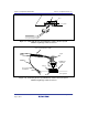
Notes: 1. When designing the 14-pin connector layout on the user board, do not place any
components within 3 mm of the H-UDI port connector.
When designing the 36-pin connector layout on the user board, do not connect other
signal lines to the H-UDI port connector.
2. The H-UDI is an interface compatible with the Joint Test Action Group (JTAG)
specifications.
(2) The pin assignments of the connector are shown in section 2 in the additional document,
Supplementary Information on Using the SHxxxx.
(3) Connect pins 2, 4, 6, 8, 10, 12, 14, 16, 18, 20, 22, 24, 26, 28, 30, 32, 33, 34, and 36 (when
using the 36-pin user system interface cable) and pins 9, 10, 12, 13, and 14 (when using the 14-
pin user system interface cable) of the H-UDI port connector to GND firmly on the PCB.
These pins are used as electrical GND and to monitor the connection of the H-UDI port
connector. Note the pin assignments of the H-UDI port connector.