
User`s manual

SuperH Family E10A-USB Emulator Section 3 Preparation before Use
R20UT0870EJ1000 Rev. 10.00 Page 23 of 292
Aug 10, 2012
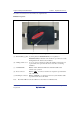
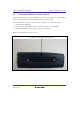
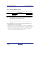
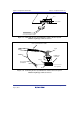
The names of each section of the emulator are explained next.
Emulator Top View:
Figure 3.3 Emulator Top View
(a) E10A-USB logo plate: A yellow plate (for HS0005KCU01H) or a red plate (for
HS0005KCU02H) dedicated for the emulator is provided to be easily
distinguished from other E-series emulators.
(b) Sliding switch cover: A cover to protect switches for setting the emulator, which is closed
to prevent incorrect operation. Be sure to close this cover during
emulation.
(c) ACTION LED: Marked ‘ACT’. When this LED is lit, the E10A-USB control
software is in operation.
(d) Host connector: Marked ‘
’. A connector for the host computer is provided at the
side of this mark.
(e) H-UDI port connector: Marked ‘USER I/F’. A connector for the user system interface cable
is provided at the side of this mark.
Note: Even if the LED is not lit, the USB is not disconnected or malfunctioned.