
User`s manual


SuperH Family E10A-USB Emulator Section 5 Debugging
R20UT0870EJ1000 Rev. 10.00 Page 107 of 292
Aug 10, 2012
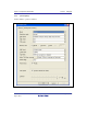
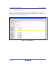
Items that can be displayed in the sheet are listed below.
[Mode] Displays the MCU/MPU name.
[Emulation mode] Selects the emulation mode at user program execution.
Select Normal to perform normal emulation.
Select No break to disable PC breakpoint or break condition
settings during emulation.
[Step option] Sets the step interrupt option.
Disable interrupts during single step execution: Disables
interrupts* during step execution.
Enable interrupts during single step execution: Enables
interrupts during step execution.
*Note: Include interrupts in a break.
[AUD clock] A clock used in acquiring AUD traces. If its frequency is set
too low, complete data may not be acquired during realtime
tracing. Set the frequency not to exceed the upper limit for the
MCU/MPU's AUD clock. The AUD clock is only needed for
using emulators that have an AUD trace function. For the
upper limit for the AUD clock, refer to section 2.2.3, Notes on
Using the JTAG (H-UDI) Clock (TCK) and AUD Clock
(AUDCK), in the additional document, Supplementary
Information on Using the SHxxxx.
[JTAG clock] A communication clock used except for acquiring AUD trace.
If its frequency is set too low, the speed of downloading will
be lowered. Set the frequency not to exceed the upper limit for
the MCU/MPU's guaranteed TCK range. For the upper limit
for TCK, refer to section 2.2.3, Notes on Using the JTAG (H-
UDI) Clock (TCK) and AUD Clock (AUDCK), in the
additional document, Supplementary Information on Using the
SHxxxx.
Note: The items that can be set in this dialog box vary according to the emulator in use. For
details, refer to the online help.