To our customers, Old Company Name in Catalogs and Other Documents On April 1st, 2010, NEC Electronics Corporation merged with Renesas Technology Corporation, and Renesas Electronics Corporation took over all the business of both companies. Therefore, although the old company name remains in this document, it is a valid Renesas Electronics document. We appreciate your understanding. Renesas Electronics website: http://www.renesas.
Notice 1. 2. 3. 4. 5. 6. 7. All information included in this document is current as of the date this document is issued. Such information, however, is subject to change without any prior notice. Before purchasing or using any Renesas Electronics products listed herein, please confirm the latest product information with a Renesas Electronics sales office.
Renesas Starter Kit for SH7216 USB Sample Code User's Manual RENESAS SINGLE-CHIP MICROCOMPUTER SH FAMILY Rev.1.00 2009.
Table of Contents Table of Contents .................................................................................................................................................. ii Chapter 1. Preface .................................................................................................................................................. 3 Chapter 2. Introduction.......................................................................................................................................
Chapter 1. Preface Cautions This document may be, wholly or partially, subject to change without notice. All rights reserved. No one is permitted to reproduce or duplicate, in any form, a part or this entire document without the written permission of Renesas Technology Europe Limited. Trademarks All brand or product names used in this manual are trademarks or registered trademarks of their respective companies or organisations. Copyright © Renesas Technology Europe Ltd. 2009. All rights reserved.
Chapter 2.Introduction The RSK USB sample code provides a basis for a developer to add USB device functionality to a system. It includes sample applications for the three most common USB Device classes * :• Human Interface Device (HID) • Communication Device Class - Abstract Control Model (CDC-ACM) • Mass Storage Class (MSC) In addition to the three defined USB classes a LibUSB sample is included.
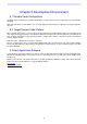
Chapter 3.Development Environment 3.1.Sample Code Configuration The Sample code is provided as a project generator with the RSK. To create the sample code project follow the instructions in the RSK Quick Start Guide. When created the sample code will contain the source for both the Target project and a Host project if applicable, including any configuration driver files. 3.2.
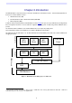
Chapter 4.USB Stack (Target) The USB software is implemented in the form of a USB stack comprising of three layers. At the bottom of the stack is a hardware abstraction layer (HAL) that provides a hardware independent API for the upper layers. In the middle is a core layer (USBCore) that handles standard device requests. At the top of the stack are the USB Device Classes consisting of HID, CDC and MSC. This top layer includes an optional API layer called the Renesas USB Function API (R_USBF).
4.2.USBCore The USBCore layer handles standard USB requests common to all USB devices during the enumeration stage. This means that a developer can concentrate on any class or vendor specific implementation. The USBCore requires initialising with the descriptors specific to the device being implemented. It uses the USBHAL, which it initialises, to access the particular HW.
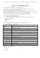
4.3. Renesas USB Function API (R_USBF) This is an optional API layer that can be used by an application rather than calling the USB Stack functions directly. It provides a generic API regardless of the USB class being used. The sample applications all use this API exclusively but as not all the functionality of the USB stack is available through this API it is realised that some applications may need to access the USB stack directly. Here are the functions that make up the R_USBF API.
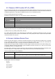
4.5.Communication Device Class The CDC ACM allows a host to see a device as a standard serial (COM) port. This is particularly useful when working with legacy applications that use serial communications. Bulk IN and Bulk OUT transfers are used for all non-setup data. The CDC module utilises the USBCore layer for the processing of all standard requests. In addition it processes the following class requests.
4.6.Mass Storage Class The MSC class has become a very popular way for devices, such as cameras and USB Pens, to share data with PCs. The reason for the success is that when the device is plugged in to a host PC it appears to the PC as just another drive and therefore users can use familiar applications such as Windows Explorer to access the data. From Windows 2000 onwards the MSC class has been supported with no need for custom drivers or ‘inf’ files.
Chapter 5.Applications 5.1.Introduction to Applications The following sections introduce the sample applications that can be used to demonstrate each of the USB solutions. The HID and LibUSB projects require specially written host applications that are supplied as both executables and as source. The CDC and MSC projects make use of standard Windows applications. All the applications require that the RSK has been programmed with the appropriate sample code for the application.
Input Report: Byte 1 Bit 0 = LED status. Bit 1 = ADC value valid indicator. Bit 2 = Switch pressed indicator. Byte 2-5 = 32 bit, little endian ADC Value. Output Report: Byte 1 Bit 0 = LED toggle request. Bit 1 = ADC read request. Bit 2 = LCD set request. Byte 2-17 = 16 ASCII Characters for LCD. An input report is sent whenever a switch on the RSK is pressed or when the host requests a report. An output report is sent whenever a user clicks on one of the dialog buttons.
5.3.Communications Device Class Application The CDC sample application demonstrates communication with a Windows PC using a standard terminal program. Windows provides a suitable application called HyperTerminal. Any other serial terminal program will be able to be used if available. Program the RSK with the CDC application and run the code as described in the RSK tutorial manual. Connect a USB cable between the host PC and the RSK.
Either type or browse to the location of the CDC project you have generated and built and then to the host/driver folder. Press next to install the CDC support. During the installation process a warning may be displayed as shown. Please choose “Continue Anyway” to install the driver. Please review the Microsoft website for details of the Windows Logo Testing programme. Windows will then complete the installation of the CDC USB driver. An additional COM port will become available to Window Applications.
Pressing SW1 on the RSK will stop this repeating message and will bring up the main menu as shown below. To demonstrate two-way communication press SW2 to put the RSK into echo mode. In this mode anything typed on the Terminal will be read by the RSK and then echoed back to the terminal. Pressing SW3 cancels this echo mode. Figure 3 - Serial communication dialog The CDC application functionality specific to USB consists of the following files:Target: usb_cdc_app.c usb_cdc_app.h Host: \PC\ CDC_Demo.
5.4.Mass Storage Class Demonstration The MSC sample demonstrates how a host can view a MSC device as an external drive. There is no additional application for this as the MSC support is inherent in Windows XP. Start the MSC sample application running on the RSK then connect the RSK to a Windows PC via a USB cable. Using Windows Explorer, or similar, look to find the new drive that Windows will have mounted. This drive is viewing the contents of the sample RAM Disk on the RSK.
5.5.LibUSB The LibUSB sample application is functionally similar to the previous HID application. The difference is that this sample includes software for a Windows host PC called RSK_LibUSB. The intention of this open source library is to provide a platform independent operating system interface allowing a device to be used on multiple operating systems with a common code base. The target RSK code is not dependant upon any external library code however it is written to support the LibUSB functionality.
Figure 5 - LibUSB application window Note: This is a screen shot after a connection has been made and the ‘Set LCD’ button and then the ‘Read ADC’ button have been used. Program the RSK with the LibUSB sample code as described in the RSK tutorial manual. Then run the code. Connect a USB cable between the host PC and the RSK. The first time the device is connected to a specific USB port Windows will detect the new device and ask for the appropriate driver.
To demonstrate that the RSK can also instigate communications you can press a switch on the RSK and this will be indicated back to the host resulting in a message being displayed on the dialog. This demonstrates that data can be sent successfully between the RSK and the PC. A fixed sized format of data has been chosen for all messages, one for OUT and one for IN: IN Message: (RSK to PC) Byte 1 Bit 0 = LED status. Bit 1 = ADC value valid indicator. Bit 2 = Switch pressed indicator.
Chapter 6.Additional Information For details on how to use High-performance Embedded Workshop (HEW), refer to the HEW manual available on the CD or installed in the Manual Navigator.
Renesas Starter Kit for SH7216 USB Sample Code User's Manual Publication Date Rev.1.00 15.December.2009 Published by: Renesas Technology Europe Ltd. Dukes Meadow, Millboard Road, Bourne End Buckinghamshire SL8 5FH, United Kingdom ©2009 Renesas Technology Europe and Renesas Solutions Corp., All Rights Reserved.
Renesas Starter Kit for SH7216 USB Sample Code User's Manual REG10J0168-0100