
User`s manual


Overview
1.6 M3A-HS11 Board Overview
Rev.1.01
Jan 31, 2008
1-6
REJ10J1262-0101
1
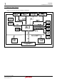
1.6 M3A-HS11 Board Overview
Figure1.6.1 shows the M3A-HS11 board overview.
< Top view of the component side >
J3
Serial Port
Connector
SW1
Power Switch
J2
H-UDI
Connector
(14-pin)
J4
Power
Supply
Connector
SW3
DIP
Switch
LED2-7
User LED
SW2
Reset
Switch
SW5
NMI
Switch
SW7
TP Switch
SW4
DIP Switch
for System
Setting
LED1
Power LED
JP4
AVREF
Select
Jumper
JP3
AVCC
Select
Jumper
JP1,JP2
Power Supply
Select Jumper
J5,J6
External
Power Supply
Connector
(Not mounted)
U1
SH7211
J1
H-UDI
Connector
(36-pin)
J7
A/D,D/A
Connector
(Not mounted)
SW6
IRQ3
Switch
< Top view of the solder side >
J12
Extension
Connector
(Not mounted)
J11
Extension
Connector
(Not mounted)
J10
Extension
Connector
(Not mounted)
J9
Extension
Connector
(Not mounted)
J8
Extension
Connector
(Not mounted)
U7
U8
U5
U3
Figure1.6.1 M3A-HS11 Board Overview