
User`s manual


18
The AUD pins are multiplexed with other pins. The AUD function cannot be used for the
initial values because they are used as other functions. To use the initial value as the AUD
function, set the AUD pins to be used from [AUD pin select] of the [Configuration] dialog box.
The emulator rewrites the registers for the pin function controller (PFC) to enable the specified
AUD pins before executing the user program. When those registers are changed by the user
program, note that the settings of the AUD pins will not be changed.
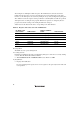
Table 2.6 shows the bits and the values corresponding to the AUD function.
Table 2.6 Registers and Values Set for the AUD Function
Pin Name of the
Port Function
AUD Function
Register and Bit to
be Set
Value to be Set
PB23 AUDCK PBCRH2[10:8] 3’b110
PB22 _AUDSYNC PBCRH2[10:8] 3’b110
PB24 AUDATA3 PBCRH2[10:8] 3’b110
PB25 AUDATA2 PBCRH2[10:8] 3’b110
PB26 AUDATA1 PBCRH2[10:8] 3’b110
PB27 AUDATA0 PBCRH2[10:8] 3’b110
10. Using WDT
The WDT does not operate during break.
11. Loading Sessions
Information in [JTAG clock] of the [Configuration] dialog box cannot be recovered by loading
sessions. Thus the TCK value will be as follows:
• When HS0005KCU01H or HS0005KCU02H is used: TCK = 2.5 MHz
12. [IO] Window
• Display and modification
For each watchdog timer register, there are two registers to be separately used for write and
read operations.