
User`s manual


Table Of Contents
- Cover
- Notes regarding these materials
- Contents
- Section 1 System Configuration
- Section 2 Connecting the Emulator to the User System
- 2.1 Connecting the Emulator to the User System
- 2.2 Connecting the Emulator to the User System by Using the EV-chip Unit
- 2.2.1 Connecting the EV-chip Unit to the Emulator
- 2.2.2 Connecting the E200F External Bus Trace Unit to the EV-chip Unit
- 2.2.3 Connecting the Probe Head to the EV-chip Unit
- 2.2.4 Connecting the E200F Emulation Memory Unit to the EV-chip Unit
- 2.2.5 Connecting the E200F External Bus Trace Unit, Emulation Memory Unit, and EV-chip Unit
- 2.2.6 Connecting the EV-chip Unit to the User System Interface Board
- 2.3 Connecting the Emulator to the User System by Using the H-UDI Port Connector
- 2.4 Installing the H-UDI Port Connector on the User System
- 2.5 Pin Assignments of the H-UDI Port Connector
- 2.6 Recommended Circuit between the H-UDI Port Connector and the MCU
- 2.7 Connecting the E200F External Bus Trace Unit with the User System
- 2.8 Installing the External Bus Trace Unit Connector
- 2.8.1 External Bus Trace Unit Connector Installed on the User System
- 2.8.2 Pin Assignments of the User System Connector
- 2.8.3 Recommended Foot Pattern
- 2.8.4 Restrictions on Component Installation
- 2.8.5 Pin Assignments of the External Bus Trace Unit Connector
- 2.8.6 Layout of the External Bus Trace Unit Connector
- 2.9 Connecting the External Bus Trace Unit to the User System
- 2.9.1 Connecting the E200F External Bus Trace Unit to the Emulator Main Unit
- 2.9.2 Connecting the E200F External Bus Trace Unit to the User System
- 2.9.3 Connecting the E200F Emulation Memory Unit to the Emulator Main Unit
- 2.9.4 Connecting the Emulation Memory Unit to the User System
- 2.9.5 Connecting the E200F External Bus Trace Unit, Emulation Memory Unit, and User System
- Section 3 Software Specifications when Using the SH7211
- 3.1 Differences between the SH7211 and the Emulator
- 3.2 Specific Functions for the Emulator when Using the SH7211
- 3.2.1 Event Condition Functions
- 3.2.2 Trace Functions
- 3.2.3 Notes on Using the JTAG (H-UDI) Clock (TCK) and AUD Clock (AUDCK)
- 3.2.4 Notes on Setting the [Breakpoint] Dialog Box
- 3.2.5 Notes on Setting the [Event Condition] Dialog Box and the BREAKCONDITION_ SET Command
- 3.2.6 Performance Measurement Function
- Section 4 User System Interface Circuits
- Colophon
3
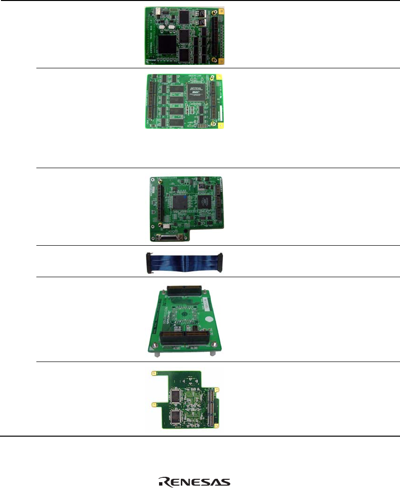
Table 1.2 Optional Components of the Emulator
Classi-
fication
Component
Appearance
Quan-
tity
Remarks
Hard-
ware
External bus trace unit 1 R0E0200F1ETU00:
Depth: 90.0 mm, Width: 125.0 mm,
Height: 15.2 mm, Mass: 100 g
Emulation memory unit
(Memory capacity:
8 Mbytes or 16 Mbytes)
1 R0E0200F1MSR00 (8 Mbytes),
R0E0200F1MSR01 (16 Mbytes):
Depth: 90.0 mm, Width: 125.0 mm,
Height: 15.2 mm,
Mass: 81 g (R0E0200F1MSR00),
85 g (R0E0200F1MSR01)
Note that it is not possible to
connect these emulation memory
units at the same time.
EV-chip unit 1 R0E572110VKK00:
Depth: 110.0 mm, Width: 125.0
mm, Height: 15.2 mm, Mass: 110 g
Trace cable 1 R0E0200F0ACC00:
Length: 300 mm, Mass: 65 g
User system interface
board
1 R0E572110CFK00:
Depth: 60.0 mm, Width: 90.0 mm,
Height: 26.0 mm, Mass: 45 g
Expansion profiling unit 1 R0E0200F0EPU00:
Depth: 98.0 mm, Width: 115.0 mm,
Height: 15.2 mm, Mass: 52 g