
User`s manual


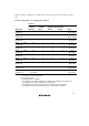


Table Of Contents
- Cover
- Notes regarding these materials
- Contents
- Section 1 System Configuration
- Section 2 Connecting the Emulator to the User System
- 2.1 Connecting the Emulator to the User System
- 2.2 Connecting the Emulator to the User System by Using the EV-chip Unit
- 2.2.1 Connecting the EV-chip Unit to the Emulator
- 2.2.2 Connecting the E200F External Bus Trace Unit to the EV-chip Unit
- 2.2.3 Connecting the Probe Head to the EV-chip Unit
- 2.2.4 Connecting the E200F Emulation Memory Unit to the EV-chip Unit
- 2.2.5 Connecting the E200F External Bus Trace Unit, Emulation Memory Unit, and EV-chip Unit
- 2.2.6 Connecting the EV-chip Unit to the User System Interface Board
- 2.3 Connecting the Emulator to the User System by Using the H-UDI Port Connector
- 2.4 Installing the H-UDI Port Connector on the User System
- 2.5 Pin Assignments of the H-UDI Port Connector
- 2.6 Recommended Circuit between the H-UDI Port Connector and the MCU
- 2.7 Connecting the E200F External Bus Trace Unit with the User System
- 2.8 Installing the External Bus Trace Unit Connector
- 2.8.1 External Bus Trace Unit Connector Installed on the User System
- 2.8.2 Pin Assignments of the User System Connector
- 2.8.3 Recommended Foot Pattern
- 2.8.4 Restrictions on Component Installation
- 2.8.5 Pin Assignments of the External Bus Trace Unit Connector
- 2.8.6 Layout of the External Bus Trace Unit Connector
- 2.9 Connecting the External Bus Trace Unit to the User System
- 2.9.1 Connecting the E200F External Bus Trace Unit to the Emulator Main Unit
- 2.9.2 Connecting the E200F External Bus Trace Unit to the User System
- 2.9.3 Connecting the E200F Emulation Memory Unit to the Emulator Main Unit
- 2.9.4 Connecting the Emulation Memory Unit to the User System
- 2.9.5 Connecting the E200F External Bus Trace Unit, Emulation Memory Unit, and User System
- Section 3 Software Specifications when Using the SH7211
- 3.1 Differences between the SH7211 and the Emulator
- 3.2 Specific Functions for the Emulator when Using the SH7211
- 3.2.1 Event Condition Functions
- 3.2.2 Trace Functions
- 3.2.3 Notes on Using the JTAG (H-UDI) Clock (TCK) and AUD Clock (AUDCK)
- 3.2.4 Notes on Setting the [Breakpoint] Dialog Box
- 3.2.5 Notes on Setting the [Event Condition] Dialog Box and the BREAKCONDITION_ SET Command
- 3.2.6 Performance Measurement Function
- Section 4 User System Interface Circuits
- Colophon

53
Table 3.10 Conditions to Be Set (cont)
Classification Item Description
[Ch1, 2, 3] list box
(cont)
Ch2 to Ch1 PA Sets the performance measurement period during
the time from the satisfaction of the condition set in
Event Condition 2 (start condition) to the
satisfaction of the condition set in Event Condition
1 (end condition).
Ch1 to Ch2 PA Sets the performance measurement period during
the time from the satisfaction of the condition set in
Event Condition 1 (start condition) to the
satisfaction of the condition set in Event Condition
2 (end condition).
[Ch4, 5] list box Sets the point-to-point of the internal trace (the start or end condition of
trace acquisition) using Event Conditions 4 and 5.
Don’t care Sets no start or end condition of trace acquisition.
I-Trace: Ch5 to Ch4
PtoP
Sets the acquisition period during the time from the
satisfaction of the condition set in Event Condition
5 (start condition) to the satisfaction of the
condition set in Event Condition 4 (end condition).
I-Trace: Ch5 to Ch4
PtoP, Power-on reset
Sets the acquisition period during the time from the
satisfaction of the condition set in Event Condition
5 (start condition) to the satisfaction of the
condition set in Event Condition 4 (end condition)
or the power-on reset.
Notes: 1. After the sequential condition and the count specification condition of Event Condition 1
have been set, break and trace acquisition will be halted if the sequential condition is
satisfied for the specified count.
2. If a reset point is satisfied, the satisfaction of the condition set in Event Condition will be
disabled. For example, if the condition is satisfied in the order of Event Condition 3, 2,
reset point, 1, the break or trace acquisition will not be halted. If the condition is
satisfied in the order of Event Condition 3, 2, reset point, 3, 2, 1, the break and trace
acquisition will be halted.
3. If the start condition is satisfied after the end condition of the performance
measurement has been satisfied, performance measurement will be restarted. For the
measurement result after a break, the measurement results during performance
measurement are added.
4. If the start condition is satisfied after the end condition has been satisfied by the point-
to-point of the internal trace, trace acquisition will be restarted.