
User`s manual


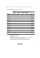


Table Of Contents
- Cover
- Notes regarding these materials
- Contents
- Section 1 System Configuration
- Section 2 Connecting the Emulator to the User System
- 2.1 Connecting the Emulator to the User System
- 2.2 Connecting the Emulator to the User System by Using the EV-chip Unit
- 2.2.1 Connecting the EV-chip Unit to the Emulator
- 2.2.2 Connecting the E200F External Bus Trace Unit to the EV-chip Unit
- 2.2.3 Connecting the Probe Head to the EV-chip Unit
- 2.2.4 Connecting the E200F Emulation Memory Unit to the EV-chip Unit
- 2.2.5 Connecting the E200F External Bus Trace Unit, Emulation Memory Unit, and EV-chip Unit
- 2.2.6 Connecting the EV-chip Unit to the User System Interface Board
- 2.3 Connecting the Emulator to the User System by Using the H-UDI Port Connector
- 2.4 Installing the H-UDI Port Connector on the User System
- 2.5 Pin Assignments of the H-UDI Port Connector
- 2.6 Recommended Circuit between the H-UDI Port Connector and the MCU
- 2.7 Connecting the E200F External Bus Trace Unit with the User System
- 2.8 Installing the External Bus Trace Unit Connector
- 2.8.1 External Bus Trace Unit Connector Installed on the User System
- 2.8.2 Pin Assignments of the User System Connector
- 2.8.3 Recommended Foot Pattern
- 2.8.4 Restrictions on Component Installation
- 2.8.5 Pin Assignments of the External Bus Trace Unit Connector
- 2.8.6 Layout of the External Bus Trace Unit Connector
- 2.9 Connecting the External Bus Trace Unit to the User System
- 2.9.1 Connecting the E200F External Bus Trace Unit to the Emulator Main Unit
- 2.9.2 Connecting the E200F External Bus Trace Unit to the User System
- 2.9.3 Connecting the E200F Emulation Memory Unit to the Emulator Main Unit
- 2.9.4 Connecting the Emulation Memory Unit to the User System
- 2.9.5 Connecting the E200F External Bus Trace Unit, Emulation Memory Unit, and User System
- Section 3 Software Specifications when Using the SH7211
- 3.1 Differences between the SH7211 and the Emulator
- 3.2 Specific Functions for the Emulator when Using the SH7211
- 3.2.1 Event Condition Functions
- 3.2.2 Trace Functions
- 3.2.3 Notes on Using the JTAG (H-UDI) Clock (TCK) and AUD Clock (AUDCK)
- 3.2.4 Notes on Setting the [Breakpoint] Dialog Box
- 3.2.5 Notes on Setting the [Event Condition] Dialog Box and the BREAKCONDITION_ SET Command
- 3.2.6 Performance Measurement Function
- Section 4 User System Interface Circuits
- Colophon

50
3.2 Specific Functions for the Emulator when Using the SH7211
In on-chip debugging mode, a reset must be input when the emulator is activated.
3.2.1 Event Condition Functions
The emulator is used to set event conditions for the following three functions:
• Break of the user program
• Internal trace
• Start or end of performance measurement
Table 3.8 lists the types of Event Condition.
Table 3.8 Types of Event Condition
Event Condition Type Description
Address bus condition (Address) Sets a condition when the address bus (data access) value
or the program counter value (before or after execution of
instructions) is matched.
Data bus condition (Data) Sets a condition when the data bus value is matched. Byte,
word, or longword can be specified as the access data size.
Bus state condition
(Bus State)
There are two bus state condition settings:
Bus state condition: Sets a condition when the data bus
value is matched.
Read/write condition: Sets a condition when the read/write
condition is matched.
Count Sets a condition when the other specified conditions are
satisfied for the specified counts.
Reset point A reset point is set when the count and the sequential
condition are specified.
Action Selects the operation when a condition (such as a break, a
trace halt condition, a trace acquisition condition, or a trigger
output) is matched.
Use the [Combination action(Sequential or PtoP)] dialog box to specify the sequential condition,
the point-to-point operation of the internal trace, and the start or end of performance measurement.