
User`s manual


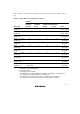


Table Of Contents
- Cover
- Notes regarding these materials
- Contents
- Section 1 System Configuration
- Section 2 Connecting the Emulator to the User System
- 2.1 Connecting the Emulator to the User System
- 2.2 Connecting the Emulator to the User System by Using the EV-chip Unit
- 2.2.1 Connecting the EV-chip Unit to the Emulator
- 2.2.2 Connecting the E200F External Bus Trace Unit to the EV-chip Unit
- 2.2.3 Connecting the Probe Head to the EV-chip Unit
- 2.2.4 Connecting the E200F Emulation Memory Unit to the EV-chip Unit
- 2.2.5 Connecting the E200F External Bus Trace Unit, Emulation Memory Unit, and EV-chip Unit
- 2.2.6 Connecting the EV-chip Unit to the User System Interface Board
- 2.3 Connecting the Emulator to the User System by Using the H-UDI Port Connector
- 2.4 Installing the H-UDI Port Connector on the User System
- 2.5 Pin Assignments of the H-UDI Port Connector
- 2.6 Recommended Circuit between the H-UDI Port Connector and the MCU
- 2.7 Connecting the E200F External Bus Trace Unit with the User System
- 2.8 Installing the External Bus Trace Unit Connector
- 2.8.1 External Bus Trace Unit Connector Installed on the User System
- 2.8.2 Pin Assignments of the User System Connector
- 2.8.3 Recommended Foot Pattern
- 2.8.4 Restrictions on Component Installation
- 2.8.5 Pin Assignments of the External Bus Trace Unit Connector
- 2.8.6 Layout of the External Bus Trace Unit Connector
- 2.9 Connecting the External Bus Trace Unit to the User System
- 2.9.1 Connecting the E200F External Bus Trace Unit to the Emulator Main Unit
- 2.9.2 Connecting the E200F External Bus Trace Unit to the User System
- 2.9.3 Connecting the E200F Emulation Memory Unit to the Emulator Main Unit
- 2.9.4 Connecting the Emulation Memory Unit to the User System
- 2.9.5 Connecting the E200F External Bus Trace Unit, Emulation Memory Unit, and User System
- Section 3 Software Specifications when Using the SH7211
- 3.1 Differences between the SH7211 and the Emulator
- 3.2 Specific Functions for the Emulator when Using the SH7211
- 3.2.1 Event Condition Functions
- 3.2.2 Trace Functions
- 3.2.3 Notes on Using the JTAG (H-UDI) Clock (TCK) and AUD Clock (AUDCK)
- 3.2.4 Notes on Setting the [Breakpoint] Dialog Box
- 3.2.5 Notes on Setting the [Event Condition] Dialog Box and the BREAKCONDITION_ SET Command
- 3.2.6 Performance Measurement Function
- Section 4 User System Interface Circuits
- Colophon
48
12. [IO] Window
• Display and modification
For each watchdog timer register, there are two registers to be separately used for write and
read operations.
Table 3.7 Watchdog Timer Register
Register Name Usage Register
WTCSR(W) Write Watchdog timer control/status register
WTCNT(W) Write Watchdog timer counter
WTCSR(R) Read Watchdog timer control/status register
WTCNT(R) Read Watchdog timer counter
WRCSR(W) Write Watchdog reset control/status register
WRCSR(R) Read Watchdog reset control/status register
• Customization of the I/O-register definition file
The internal I/O registers can be accessed from the [IO] window. However, note the following
when accessing the SDMR register of the bus state controller. Before accessing the SDMR
register, specify addresses to be accessed in the I/O-register definition file (SH7211.IO) and
then activate the High-performance Embedded Workshop. After the I/O-register definition file
is created, the MCU’s specifications may be changed. If each I/O register in the I/O-register
definition file differs from addresses described in the hardware manual, change the I/O-register
definition file according to the description in the hardware manual. The I/O-register definition
file can be customized in accordance to its format. However, the emulator does not support the
bit-field function.
• Verification
In the [IO] window, the input values cannot be verified.
13. Illegal Instructions
Do not execute illegal instructions with STEP-type commands.