
User`s manual


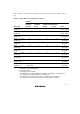


Table Of Contents
- Cover
- Notes regarding these materials
- Contents
- Section 1 System Configuration
- Section 2 Connecting the Emulator to the User System
- 2.1 Connecting the Emulator to the User System
- 2.2 Connecting the Emulator to the User System by Using the EV-chip Unit
- 2.2.1 Connecting the EV-chip Unit to the Emulator
- 2.2.2 Connecting the E200F External Bus Trace Unit to the EV-chip Unit
- 2.2.3 Connecting the Probe Head to the EV-chip Unit
- 2.2.4 Connecting the E200F Emulation Memory Unit to the EV-chip Unit
- 2.2.5 Connecting the E200F External Bus Trace Unit, Emulation Memory Unit, and EV-chip Unit
- 2.2.6 Connecting the EV-chip Unit to the User System Interface Board
- 2.3 Connecting the Emulator to the User System by Using the H-UDI Port Connector
- 2.4 Installing the H-UDI Port Connector on the User System
- 2.5 Pin Assignments of the H-UDI Port Connector
- 2.6 Recommended Circuit between the H-UDI Port Connector and the MCU
- 2.7 Connecting the E200F External Bus Trace Unit with the User System
- 2.8 Installing the External Bus Trace Unit Connector
- 2.8.1 External Bus Trace Unit Connector Installed on the User System
- 2.8.2 Pin Assignments of the User System Connector
- 2.8.3 Recommended Foot Pattern
- 2.8.4 Restrictions on Component Installation
- 2.8.5 Pin Assignments of the External Bus Trace Unit Connector
- 2.8.6 Layout of the External Bus Trace Unit Connector
- 2.9 Connecting the External Bus Trace Unit to the User System
- 2.9.1 Connecting the E200F External Bus Trace Unit to the Emulator Main Unit
- 2.9.2 Connecting the E200F External Bus Trace Unit to the User System
- 2.9.3 Connecting the E200F Emulation Memory Unit to the Emulator Main Unit
- 2.9.4 Connecting the Emulation Memory Unit to the User System
- 2.9.5 Connecting the E200F External Bus Trace Unit, Emulation Memory Unit, and User System
- Section 3 Software Specifications when Using the SH7211
- 3.1 Differences between the SH7211 and the Emulator
- 3.2 Specific Functions for the Emulator when Using the SH7211
- 3.2.1 Event Condition Functions
- 3.2.2 Trace Functions
- 3.2.3 Notes on Using the JTAG (H-UDI) Clock (TCK) and AUD Clock (AUDCK)
- 3.2.4 Notes on Setting the [Breakpoint] Dialog Box
- 3.2.5 Notes on Setting the [Event Condition] Dialog Box and the BREAKCONDITION_ SET Command
- 3.2.6 Performance Measurement Function
- Section 4 User System Interface Circuits
- Colophon

46
9. Multiplexing the AUD Pins in On-Chip Debugging Mode
The AUD pins are multiplexed as shown in table 3.5.
Table 3.5 Multiplexed Functions
Function 1 Function 2
WSCK TCK
WTXD TMS
WRXD _TRST
PB30/_UBCTRG/_IRQOUT _ASEBRKAK/_ASEBRK
PB22/RXD2/TCLKD/DACK2/FRAME _AUDSYNC
PB23/TXD2/TCLKC/DREQ2 AUDCK
PB24/RXD3/TCLKB/IRQ2/TEND1 AUDATA3
PB25/TXD3/TCLKA/IRQ3/DACK1 AUDATA2
PB26/SCK3/TIOC2B/DREQ1 AUDATA1
PB27/TXD3/TIOC2A/TEND0 AUDATA0
When the emulator is connected in on-chip debugging mode, function 1 cannot be used
because the emulator uses the pins that TCK, TMS, _TRST, and _ASEBRKAK/_ASEBRK
have been multiplexed. Function 1 can be used when the pins that AUD has been multiplexed
are not connected to the emulator in on-chip debugging mode.
The AUD pins are multiplexed with other pins. The AUD function cannot be used for the
initial values because they are used as other functions. To use the initial value as the AUD
function, set the AUD pins to be used from [AUD pin select] of the [Configuration] dialog box.
The emulator rewrites the registers in the pin function controller (PFC) to enable the specified
AUD pins before executing the user program. When those registers are changed by the user
program, take care so that the settings of the AUD pins is not changed.
Table 3.6 shows the bits and the values corresponding to the AUD function.