
User`s manual


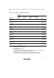


Table Of Contents
- Cover
- Notes regarding these materials
- Contents
- Section 1 System Configuration
- Section 2 Connecting the Emulator to the User System
- 2.1 Connecting the Emulator to the User System
- 2.2 Connecting the Emulator to the User System by Using the EV-chip Unit
- 2.2.1 Connecting the EV-chip Unit to the Emulator
- 2.2.2 Connecting the E200F External Bus Trace Unit to the EV-chip Unit
- 2.2.3 Connecting the Probe Head to the EV-chip Unit
- 2.2.4 Connecting the E200F Emulation Memory Unit to the EV-chip Unit
- 2.2.5 Connecting the E200F External Bus Trace Unit, Emulation Memory Unit, and EV-chip Unit
- 2.2.6 Connecting the EV-chip Unit to the User System Interface Board
- 2.3 Connecting the Emulator to the User System by Using the H-UDI Port Connector
- 2.4 Installing the H-UDI Port Connector on the User System
- 2.5 Pin Assignments of the H-UDI Port Connector
- 2.6 Recommended Circuit between the H-UDI Port Connector and the MCU
- 2.7 Connecting the E200F External Bus Trace Unit with the User System
- 2.8 Installing the External Bus Trace Unit Connector
- 2.8.1 External Bus Trace Unit Connector Installed on the User System
- 2.8.2 Pin Assignments of the User System Connector
- 2.8.3 Recommended Foot Pattern
- 2.8.4 Restrictions on Component Installation
- 2.8.5 Pin Assignments of the External Bus Trace Unit Connector
- 2.8.6 Layout of the External Bus Trace Unit Connector
- 2.9 Connecting the External Bus Trace Unit to the User System
- 2.9.1 Connecting the E200F External Bus Trace Unit to the Emulator Main Unit
- 2.9.2 Connecting the E200F External Bus Trace Unit to the User System
- 2.9.3 Connecting the E200F Emulation Memory Unit to the Emulator Main Unit
- 2.9.4 Connecting the Emulation Memory Unit to the User System
- 2.9.5 Connecting the E200F External Bus Trace Unit, Emulation Memory Unit, and User System
- Section 3 Software Specifications when Using the SH7211
- 3.1 Differences between the SH7211 and the Emulator
- 3.2 Specific Functions for the Emulator when Using the SH7211
- 3.2.1 Event Condition Functions
- 3.2.2 Trace Functions
- 3.2.3 Notes on Using the JTAG (H-UDI) Clock (TCK) and AUD Clock (AUDCK)
- 3.2.4 Notes on Setting the [Breakpoint] Dialog Box
- 3.2.5 Notes on Setting the [Event Condition] Dialog Box and the BREAKCONDITION_ SET Command
- 3.2.6 Performance Measurement Function
- Section 4 User System Interface Circuits
- Colophon

45
7. Memory Access to the External Flash Memory Area
The emulator can download the load module to the external flash memory area (for details,
refer to section 6.21, Download Function to the Flash Memory Area, in the SH-2A, SH-2
E200F Emulator User’s Manual). Other memory write operations are enabled for the RAM
area. Therefore, an operation such as memory write or a BREAKPOINT should be set only for
the RAM area.
8. ROM Cache
For ROM cache in the MCU, the emulator operates as shown in table 3.4.
Table 3.4 Operation for ROM Cache
Function Operation
Write and erase Writes or erases all contents of ROM cache.
Memory read Accesses the disabled cache area to read the content of internal flash
memory.