
User`s manual

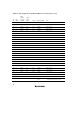

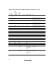


Table Of Contents
- Cover
- Notes regarding these materials
- Contents
- Section 1 System Configuration
- Section 2 Connecting the Emulator to the User System
- 2.1 Connecting the Emulator to the User System
- 2.2 Connecting the Emulator to the User System by Using the EV-chip Unit
- 2.2.1 Connecting the EV-chip Unit to the Emulator
- 2.2.2 Connecting the E200F External Bus Trace Unit to the EV-chip Unit
- 2.2.3 Connecting the Probe Head to the EV-chip Unit
- 2.2.4 Connecting the E200F Emulation Memory Unit to the EV-chip Unit
- 2.2.5 Connecting the E200F External Bus Trace Unit, Emulation Memory Unit, and EV-chip Unit
- 2.2.6 Connecting the EV-chip Unit to the User System Interface Board
- 2.3 Connecting the Emulator to the User System by Using the H-UDI Port Connector
- 2.4 Installing the H-UDI Port Connector on the User System
- 2.5 Pin Assignments of the H-UDI Port Connector
- 2.6 Recommended Circuit between the H-UDI Port Connector and the MCU
- 2.7 Connecting the E200F External Bus Trace Unit with the User System
- 2.8 Installing the External Bus Trace Unit Connector
- 2.8.1 External Bus Trace Unit Connector Installed on the User System
- 2.8.2 Pin Assignments of the User System Connector
- 2.8.3 Recommended Foot Pattern
- 2.8.4 Restrictions on Component Installation
- 2.8.5 Pin Assignments of the External Bus Trace Unit Connector
- 2.8.6 Layout of the External Bus Trace Unit Connector
- 2.9 Connecting the External Bus Trace Unit to the User System
- 2.9.1 Connecting the E200F External Bus Trace Unit to the Emulator Main Unit
- 2.9.2 Connecting the E200F External Bus Trace Unit to the User System
- 2.9.3 Connecting the E200F Emulation Memory Unit to the Emulator Main Unit
- 2.9.4 Connecting the Emulation Memory Unit to the User System
- 2.9.5 Connecting the E200F External Bus Trace Unit, Emulation Memory Unit, and User System
- Section 3 Software Specifications when Using the SH7211
- 3.1 Differences between the SH7211 and the Emulator
- 3.2 Specific Functions for the Emulator when Using the SH7211
- 3.2.1 Event Condition Functions
- 3.2.2 Trace Functions
- 3.2.3 Notes on Using the JTAG (H-UDI) Clock (TCK) and AUD Clock (AUDCK)
- 3.2.4 Notes on Setting the [Breakpoint] Dialog Box
- 3.2.5 Notes on Setting the [Event Condition] Dialog Box and the BREAKCONDITION_ SET Command
- 3.2.6 Performance Measurement Function
- Section 4 User System Interface Circuits
- Colophon

31
Table 2.4 Pin Assignments of the External Bus Trace Unit Connector (cont)
Pin
No.
I/O
(CONT)
E200F
Trace I/F
Connector
Pin Name
SH7211
Signal
Name
Voltage
Meaning of Signal
Note
167 I CS4IN-N _CS4 3.3 V Chip select signal Same as above.
168 I CS5IN-N _CS5 3.3 V Chip select signal Same as above.
169 I CS6IN-N _CS6 3.3 V Chip select signal Same as above.
170 I CS7IN-N _CS7 3.3 V Chip select signal Same as above.
171 I CS8IN-N _CS8 3.3 V Chip select signal Same as above.
172 I CS9IN-N N.C -
173 O EM0OUT-N N.C -
174 O EM1OUT-N N.C -
175 O EM2OUT-N N.C -
176 O EMEN-P N.C -
177 I VCCQ VCCQ 3.3 V Power supply for user
system: 3.3 V
Connect VCCQ.
178 I VCCQ VCCQ 3.3 V Power supply for user
system: 3.3 V
Connect VCCQ.
179 I VCCQ VCCQ 3.3 V Power supply for user
system: 3.3 V
Connect VCCQ.
180 I GND GND GND Input low level or connect GND.
Note: Voltage-applying level: H: 2.4V to VCCQ, L: GND to 0.4V.
N.C.: Do not connect anything to this pin. Fix the unused signals of the address or data bus to high or low level.
For multiplexed pins, connect a pin such that the signal name and the signal used by the user are matched.
Be sure to connect the signals written as 'necessary', GND, and VCCQ to operate the emulator normally.
If a signal input pin such as an address pin is fixed to high or low (GND) level, the actual CPU access may differ in trace display or
condition access.